Welcome to my multipart series on how to do basic hardware hacks using the Arduino. By the end of this series you should be able to make something electronic in your house light up, whistle, or spin in response to something that happens on the internet. This series is intended for someone that doesn’t own a soldering iron, and if they’ve used the Arduino, hasn’t gone beyond making an LED light up.
Am I the best person to teach you this stuff?
I am a web developer who specializes in cloud-based containers and serverless applications. I am not an electrical engineer, but I assure you that even if a basic circuit feels intimidating, I, a humble code witch, was able to learn all of this rather easily. Being self taught means that I can now teach you in a way that is simple, straightforward, and easy to learn. Following this guide series should take no more than a few hours.
Materials
Just a computer and a free Tinkercad account (sign up link below)! While you _can _use a tablet or chromebook, a desktop or laptop will be much easier for you. This course will use only virtual tools to teach you. Once you're ready to start hacking hardware, you'll need to buy some supplies, but for now all you'll need is your free Tinkercad account.
Let’s get started
Our goal for this first session is to build a circuit that takes power from a battery and sends lights to an LED. While this is a very simple circuit to build, doing so will teach us enough about circuit design to create a complete Arduino project.
Log in to Tinkercad. If you are creating a new account, Tinkercad will take you through a 3D design tutorial. These tools are not necessary for our purposes as we'll be working with Circuits, so feel free to skip the tutorial if you want to. Instead, click on the Tinkercad logo in the top left corner. Then go to ‘Circuits > Create new Circuit’
On the right you’ll see a panel of components you can use. Scroll down or search for a breadboard, and drag it into the workspace.
Meet the breadboard
In the electronics you use every day, electricity is conducted by wires that are soldered together, or by copper ‘traces’ that are manufactured as part of a printed circuit board. Neither of these is a good way to build a prototype, so electrical engineers invented the breadboard.
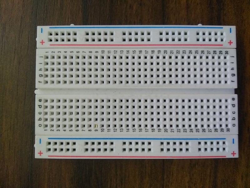
Image credit: Maskaravivek
The breadboard has hundreds of little socket connections that let you connect two or more components without soldering them together. The ones we use in Tinkercad will work exactly like the ones in real life do, and if you want to follow this tutorial with real components all the circuits will work the same way. The most important thing to know about a breadboard is how the little plugs are connected: each vertical column of plugs is connected to the others, and the rows on top and bottom (usually marked with a ‘+’ and a ‘-’) are all connected horizontally. The horizontal rows are where we supply power and are generally called ‘rails’.
Tinkercad helpfully highlights this when you hover over a column
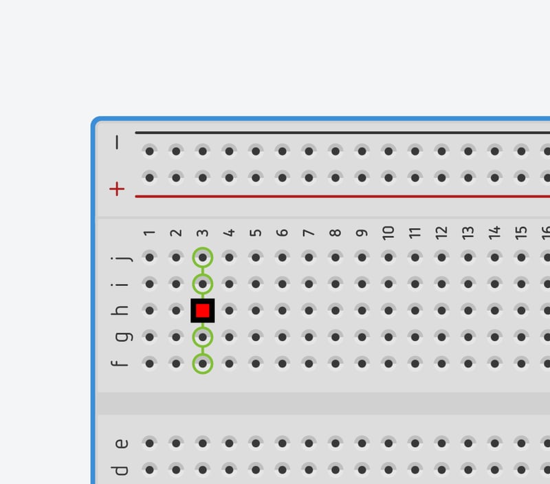
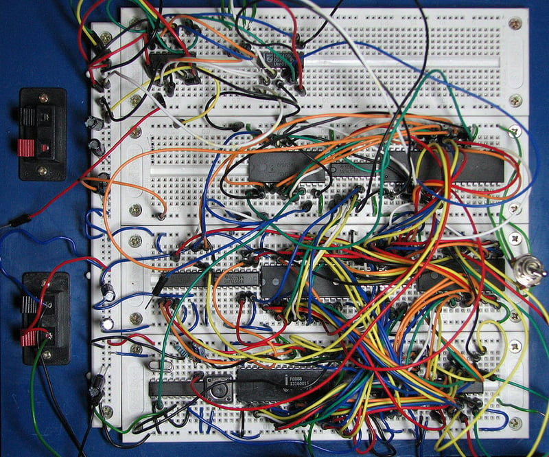
This small piece of plastic and copper lets us create _very _complex circuits without any soldering, and lets us change things very quickly
Okay let’s get this LED powered!
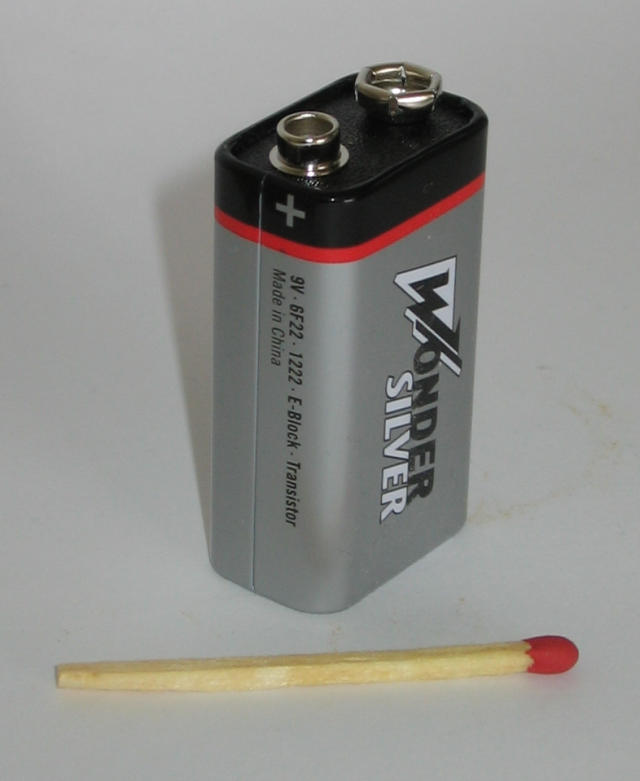
Meet the Battery
We’re going to use a 9-volt battery for this exercise, which you may remember licking in your childhood days. (Or maybe that was just me?)
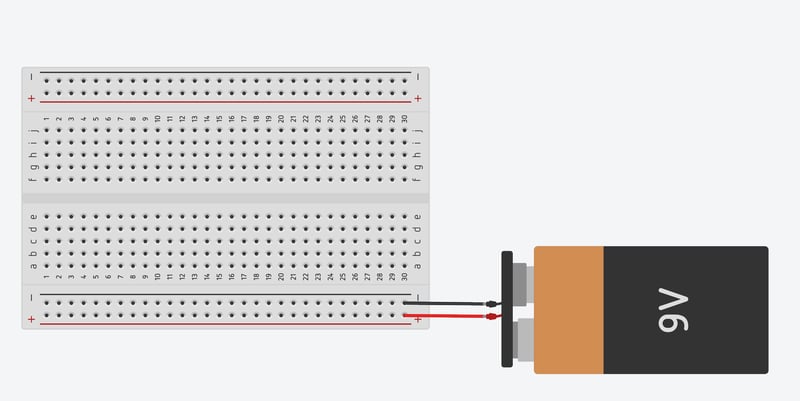
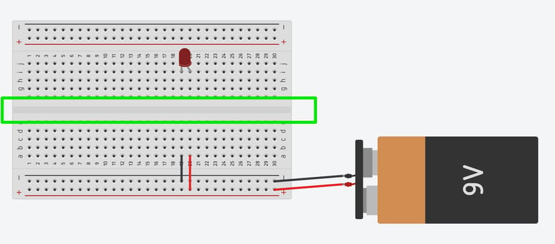
What else can we say about them? It’s a battery! Start by hooking the positive and negative to the positive and negative ‘rails’ at the bottom of the breadboard. The color of the wire doesn’t effect the circuit, but for clarity we’ll keep the positive red and the negative black:
Let’s hook it up to the LED
Meet the LED
LED stands for light emitting diode, and while we’re all familiar with their light-giving ways, you may be less familiar with the ‘diode’ part. A diode is an electrical component that only lets current flow in one direction. A real-world LED has one wire ‘leg’ that’s longer than the other to show which side needs to be connected to the positive power direction (this part, that has to be connected to ‘+’, is called the anode, but I won't use this term too much). In our virtual LED one side has a little ‘bend’ in it to show you it’s the longer wire.
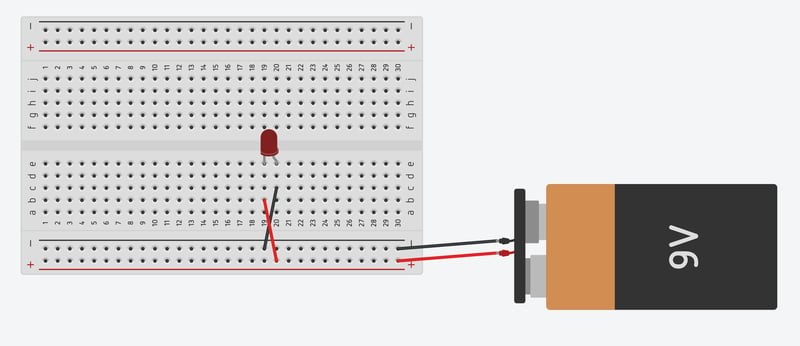
Hooking up the LED backwards will mean the LED doesn’t light up and, essentially, nothing happening:
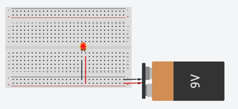
Okay, let’s straighten out those wires and start our LED! Hook the black rail to the left-hand shorter leg and the red to the longer right leg, and hit ‘start simulation’ to turn on the power. You’ll see your LED light up!
Something here doesn’t look quite right
You’ll see a sort of ‘explosion’ graphic over your LED, and if you hover over it Tinkercad will show you a tooltip saying that too many amps are being passed through the LED. If this were a real LED we’d have to throw this part away and find a new one. Thankfully they only cost a few cents.
Controlling the ‘flow’ of electricity
This would be a good place for me to write about 900 words about resistance, ohm’s law, and the relationship of voltage, amperage, and the amount of electricity you need to use. But we just want to make an LED light up, so I’m going to start with the solution: we need a resistor to control how much power we use.
Move your LED to the upper section of the breadboard, directly above where it was before. The ‘gap’ at the middle of your breadboard breaks up each vertical column meaning right now your LED isn’t going to power on:
Drag a resistor off the parts panel and add it above the black wire, such that it jumps the middle gap, then drag your red wire so it connects to the LED.
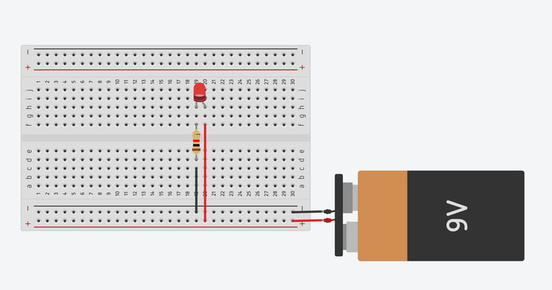
Now if you click ‘start simulation’ we’ll finally have a circuit that lights an LED
To get the first instinctive sense of what resistance does to your circuit, click the resistor and edit its resistance value. Resistors will default to one kiloohm (1kΩ) in Tinkercad. If you lower the resistance to .5, the LED gets much brighter. Raise the resistance to 2 kΩ and the LED gets quite a bit dimmer.
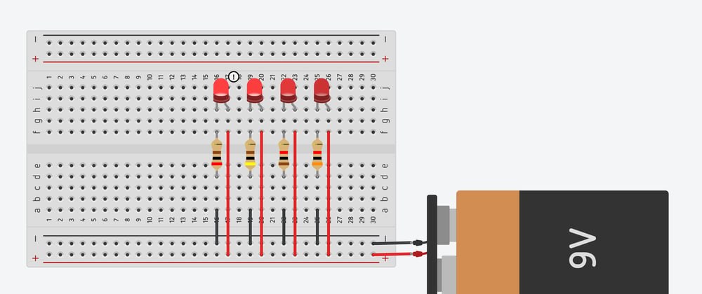
This can be difficult to see, so let’s harness the power of of the breadboard to hook up several LEDs at once with different values of resistor for each one:
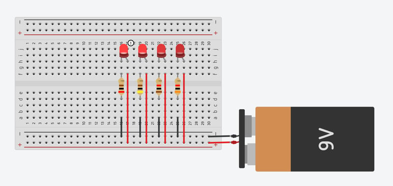
Here we’ve put in LED’s from 0.2kΩ to 3kΩ on the far right. The lowest resistance value at the left gives the LED so much power that there’s a little tooltip in Tinkercad saying that this may damage the LED. Neat!
There are a number of things I’d like to note about the image above:
- Resistors’ ohm rating is indicated by their colored stripes, which we won’t need for this tutorial but is still just kind of cool
- In my version I’ve arranged the battery, components, and wires in a way that I think looks neat and is easy to understand. There are endless ways to arrange components and wires on a breadboard into circuits that do the same thing but look different.
Part 2 is coming later this week where we'll add the arduino to our circuits!


Top comments (3)
You are the best person to teach all the stuff!
HAHAHHAHAHAH , I can't tell how many of those boards ended up on fire in the lab.
Also broken resistor legs.
You haven’t lived til you’ve connected a capacitor backwards