This is the second post along my journey to creating a biometric password manager. For an overview of the project, read this post.
Because I want to program my final product in Rust - to get that memory safety and slightly more ergonomic bare-metal programming - I first need to learn how to use Rust on a microcontroller. To help me, I will be writing some relatively simple firmware programs for the Nucleo-F446RE board that I got for the whole project.
Prepare for boarding
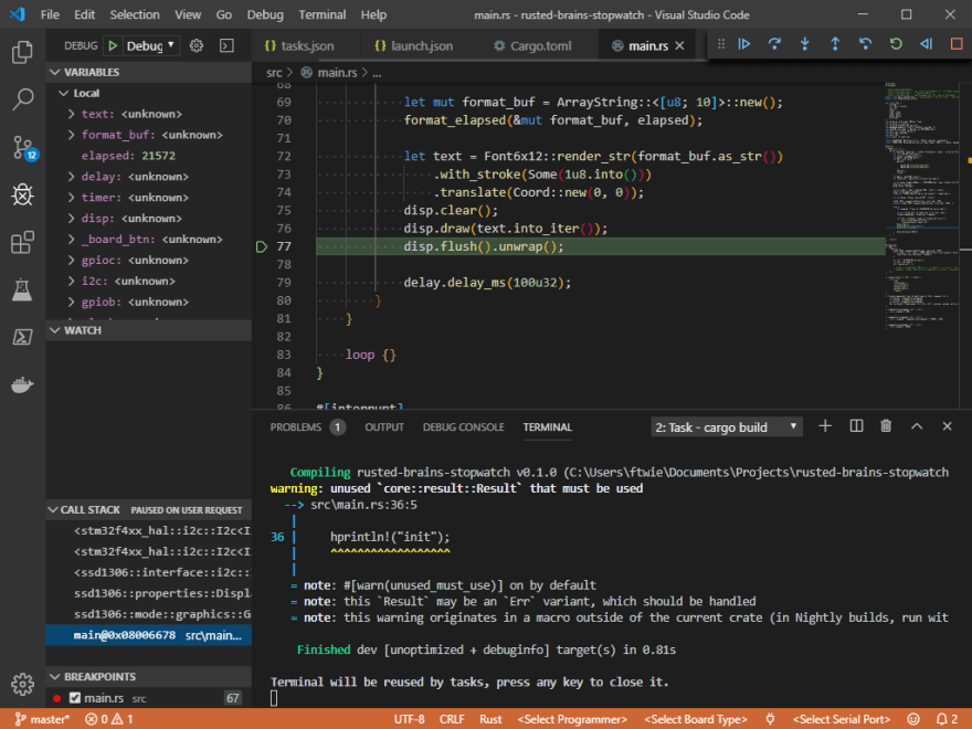
Before you embark on some crazy big project with two big unknowns, you should ask one question - will the two big unknowns work together? For Rust and ARM-based microcontrollers, the answer is largely yes. According to the Rust platform support page, the thumbv7em-none-eabi architecture is supported, albeit without the guarantee of Rust tests passing for each build. For now, that's good enough. The next question is, what is the best toolchain? Because ARM is such a broad platform, even if you focus on Cortex-M microcontrollers, there are loads of different options for compiling, flashing, and debugging your code. However most of them are expensive and designed for C/C++. The toolchain I'm using for this project is more of a pick-and-mix than a specialized IDE:
- Visual Studio Code for editing, with the Rust extension
- GCC + GDB from ARM - mostly for the GDB. Make sure you get the Cortex-R/M version
- The
thumbv7em-none-eabitarget, installed usingrustup target add thumbv7em-none-eabi - OpenOCD for connecting GDB to the ST-Link debug hardware present on the Nucleo boards. You can get binaries from the GNU MCU Eclipse OpenOCD fork.
- The native debugger extension for debugging in VS Code
When combined, these items provide a rather streamlined coding and debugging experience.
Finding libraries
crates.io is the search engine for Rust packages. For hardware support, the libraries are mercifully named closely after what they do - stm32f4xx-hal is a general-purpose abstraction layer crate for STM32F4xx microcontrollers, and ssd1306 is a driver for the SSD1306 display chip present in all these cheap 128x64 and 128x32 OLED displays you can get from the usual suspects. We will be using both of these later on.
Reading datasheets
Because this is an embedded project, and we are not using Arduino or Mbed, we need to know at least a little about how the specific chip works. These can be found on the STM32F446RE page on ST.com. There is a number of documents on this page, but the most important are those two:
Combined, these two will give you a detailed picture of the peripherals and clock configuration options available on the MCU. On the other hand, they are vast, complex, and utterly dull - take the HAL option if you can. The important part is that these two should be treated as reference documents - don't read them cover to cover, grep through them to find what you need. Unless you have no idea how the chip works to begin with, in which case - ask yourself, what peripherals could you string together to achieve what you need?
What we will be making
The project discussed in this post will be a simple stopwatch. The requirements are as follows:
- The stopwatch starts at 00:00.000
- Pressing the user button on the board starts the stopwatch
- Pressing the button again stops the stopwatch
- No lap or reset - to reset the stopwatch, an MCU reset will be required.
- Stopwatch resolution should be 1ms
- The screen should be updated at least every 100ms
To meet them, the following peripherals will be used:
- A hardware timer firing an interrupt every 1ms
- SysTick for providing slightly less accurate display update timing
- I2C for interfacing with the display
- A GPIO input to handle the button
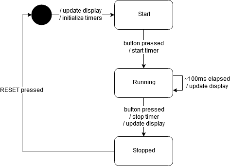
And because this is an embedded system, we should produce a state transition diagram to help us model the thing. For something as simple as this stopwatch, the value of creating one is minimal, but for more complex systems these become very useful for trying to figure out what states the system can reach, and to get an overview of how it behaves overall.
Iteration 1: A non-interactive stopwatch
This is a stopwatch that is even dumber than the final product of this post - it will simply count how much time has passed since the last reset and display it on the screen. It doesn't mean there aren't quite a few things going on already!
For one, we have to set up the internal clocks. I chose to run this example at a respectable core frequency of 48MHz (which is probably overkill but it's easy to set up like that).
// Code is for example only and may not run.
#![no_std]
#![no_main]
extern crate panic_semihosting;
extern crate stm32f4xx_hal as hal;

use crate::hal::{
    prelude::*,
    rcc::{Rcc, Clocks},
    stm32,
};
use cortex_m_rt::{entry};

#[entry]
fn main() -> ! {
    if let (Some(dp), Some(cp)) = (stm32::Peripherals::take(), cortex_m::Peripherals::take()) {
        let rcc = dp.RCC.constrain();
        let clocks = setup_clocks(rcc);
    }

    loop {}
}

fn setup_clocks(rcc: Rcc) -> Clocks {
    return rcc
        .cfgr
        .hclk(48.mhz())
        .sysclk(48.mhz())
        .pclk1(24.mhz())
        .pclk2(24.mhz())
        .freeze();
}
A few things of note already:
- Notice that
#[entry]annotation onmain? It means that it will be the user program's direct entry point, called right after the RAM is initialised. - The function never returns - because there is nothing to return to. No operating system to clean up your program after it exits, no processes, nothing. When you're done, just enter an infinite loop.
- Following from (2) - there's no standard library and no allocator. Vector's won't work. Formatting strings requires external crates. It's a weird world.
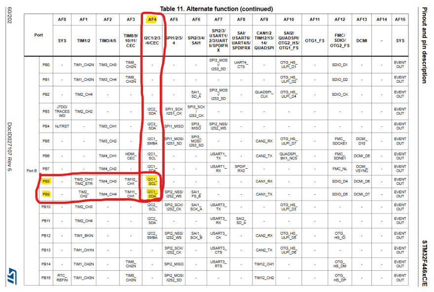
Alright, that set up our first physical peripheral - the I2C display. To do that, I first have to initialise I2C. And to do that, I have to find two pins that can be used as I2C SCL and SDA lines. To do that, you need to open the datasheet of the specific MCU you have and do some text searches for "SCL" and "SDA" until you know which pins map to which I2C (there are several), and which alternate function the pins need to be in in order to connect to the I2C peripheral. I will be using pins 8 and 9 on port B because that's what strikes my fancy (and those pins are conveniently broken out and labelled as SCL and SDA on the Nucleo board). And they need to be in alternate function 4 because that's what the designers at STMicroelectronics thought will be suitable.
The Rust code, then, to take those GPIO pins and connect them to I2C1 is as follows:
let gpiob = dp.GPIOB.split();
let i2c = I2c::i2c1(
    dp.I2C1,
    (
        gpiob.pb8.into_alternate_af4(),
        gpiob.pb9.into_alternate_af4(),
    ),
    400.khz(),
    clocks,
);
Now, if you're slightly confused about which alternate function you need, Rust will helpfully tell you when you're wrong, and possibly even what you need to do to fix it. It's nice like that.
Now that I have I2C up and running, it's time to set up the display itself. It's easy.
let mut disp: GraphicsMode<_> = SSD1306Builder::new().connect_i2c(i2c).into();
disp.init().unwrap();
disp.flush().unwrap();
The ssd1306 library contains some basic text and drawing functions, so you don't have to worry about writing individual pixels if you don't want to. I also have a simple, display-only example up on github.
And then I had to set up the timer and spend quite a lot of time trying to figure out how exactly I was going to do it, and then even more time debugging why my interrupt service routines are being called back to back. So:
- You have to clear the interrupt flag on the peripheral
- At the time of writing, there was no way to do that with the HAL
- The actual code is very simple, but because it wasn't part of the HAL I had to first try it as
unsafe - So I went ahead and opened a PR, which got accepted, merged, and released during writing. Thanks!
Furthermore, the way to share data between the ISRs and the main thread is suitably arcane. However, it looks something like this:
use core::cell::{Cell, RefCell};
use core::ops::DerefMut;
use crate::hal::{interrupt, timer::{Timer, Event}};
use cortex_m::interrupt::{Mutex, free};


// Outside of main():
// Set up two global, mutable, concurrency-safe containers. One is
// simple and holds our milliseconds value. The other holds the
// TIM2 reference which will be available after the setup has finished.
static ELAPSED_MS: Mutex<Cell<u32>> = Mutex::new(Cell::new(0u32));
static TIMER_TIM2: Mutex<RefCell<Option<Timer<stm32::TIM2>>>> = Mutex::new(RefCell::new(None));


// Inside main()
let mut timer = Timer::tim2(dp.TIM2, 1.khz(), clocks);
timer.listen(Event::TimeOut);
// Free enters a critical section and this is necessary to access
// references held by a Mutex<T>.
free(|cs| *TIMER_TIM2.borrow(cs).borrow_mut() = Some(timer));

stm32::NVIC::unpend(stm32f4xx_hal::interrupt::TIM2);
// Unmasking interrupts is inherently unsafe, but this one's fine
unsafe { stm32::NVIC::unmask(stm32f4xx_hal::interrupt::TIM2); };


// The ISR
#[interrupt]
fn TIM2() {
    free(|cs| {
        if let Some(ref mut tim2) = TIMER_TIM2.borrow(cs).borrow_mut().deref_mut() {
            // Clear the interrupt flag so that the ISR does not get retriggered
            // immediately.
            tim2.clear_interrupt(Event::TimeOut);
        }

        let cell = ELAPSED_MS.borrow(cs);
        let val = cell.get();
        cell.replace(val + 1);
    });
}


// Back inside main(), this time accessing the elapsed value
let elapsed = free(|cs| ELAPSED_MS.borrow(cs).get());
This is quite a lot of work too, but that's what you get with concurrency and interrupts. First, we make sure that both the main thread and the ISR can access the elapsed milliseconds value safely - adding critical sections where necessary in order to prevent situations where the ISR is writing the value while the main thread is about to read it. A similar protection has to be applied to the TIMER_TIM2 variable which holds the timer state, since the ISR will need to access it to clear the interrupt. Then, the interrupt has to be enabled, and in two places - one is TIM2 itself, and the other is the NVIC - Nested Vector Interrupt Controller - which triggers ISRs. The ISR then needs to clear the condition that caused the interrupt somehow - otherwise the interrupt will get retriggered immediately. In this case, the clear_interrupt method is called on TIM2.
However at this point, we have our very basic stopwatch! You can see a snapshot of the code on github. And a demo in this crappy gif!
Iteration 2: User input
Alright, so with that first hurdle out of the way - what do we need to make the user button work? Well, we need three things:
- We need to make the button pin an input. I use a pull-up resistor so that when the button is not pressed, the line is high, and when it's pressed, it goes low.
- We need a way to tell that the button is being pressed. I used, for my sins, another interrupt.
- We need something to keep track of the state we're in - recall the transition diagram from above.
So, for #1:
let gpioc = dp.GPIOC.split();
let mut board_btn = gpioc.pc13.into_pull_up_input();
board_btn.make_interrupt_source(&mut dp.SYSCFG);
board_btn.enable_interrupt(&mut dp.EXTI);
board_btn.trigger_on_edge(&mut dp.EXTI, Edge::FALLING);
Very nice API. The HAL really shines here. I did however need to make the Some(dp) a Some(mut dp).
For #2, things get a little more sketchy. I needed to put both the EXTI and the button into global RefCells. Check out that >>>>>!
static EXTI: Mutex<RefCell<Option<stm32::EXTI>>> = Mutex::new(RefCell::new(None));
static BUTTON: Mutex<RefCell<Option<PC13<Input<PullUp>>>>> = Mutex::new(RefCell::new(None));
What is EXTI, anyway? It's a thing (peripheral?) on STM32 microcontrollers which handles EXternally Triggered Interrupts. Or at least I think that's how the initialism works. Honestly the configuration options for the EXTI confuse me to no end and I dread to think what I'd need to do if I have several buttons I want to put interrupts on - as they may go into the same interrupt. Not in this case - I only have one button, so I can just cheat and treat the whole interrupt as coming from that one button press.
#[interrupt]
fn EXTI15_10() {
    free(|cs| {
        let mut btn_ref = BUTTON.borrow(cs).borrow_mut();
        let mut exti_ref = EXTI.borrow(cs).borrow_mut();
        if let (Some(ref mut btn), Some(ref mut exti)) = (btn_ref.deref_mut(), exti_ref.deref_mut())
        {
            btn.clear_interrupt_pending_bit(exti);
        }
    });
}
I still need to clear the interrupt, and then turn that button press into something useful. Which is what #3 is about. I created an enum for the state, and then added it to the global state. I needed to add the Clone and Copy traits in order to get it to work with a Cell, but luckily those can just be derived automatically.
#[derive(Clone, Copy)]
enum StopwatchState {
    Ready,
    Running,
    Stopped,
}

static STATE: Mutex<Cell<StopwatchState>> = Mutex::new(Cell::new(StopwatchState::Ready));
Then, inside the button interrupt handler, I check the state, transition to the next one, and fire appropriate actions. In general this shouldn't be done in an ISR, however because my main thread purposefully sleeps 100ms every cycle, I needed a place where stopping the stopwatch would actually give the correct time. So into the ISR it goes:
let state = STATE.borrow(cs).get();
// Run the state machine in an ISR - probably not something you want to do in most
// cases but this one only starts and stops TIM2 interrupts
match state {
    StopwatchState::Ready => {
        stopwatch_start(cs);
        STATE.borrow(cs).replace(StopwatchState::Running);
    }
    StopwatchState::Running => {
        stopwatch_stop(cs);
        STATE.borrow(cs).replace(StopwatchState::Stopped);
    }
    StopwatchState::Stopped => {}
}
And what are stopwatch_start and stopwatch_stop? You can actually activate and deactivate TIM2 at will, however I felt like it would take too much effort for this example. Instead I do the next best thing and turn the interrupts on and off:
fn stopwatch_start<'cs>(cs: &'cs CriticalSection) {
    ELAPSED_MS.borrow(cs).replace(0);
    unsafe {
        stm32::NVIC::unmask(hal::interrupt::TIM2);
    }
}

fn stopwatch_stop<'cs>(_cs: &'cs CriticalSection) {
    stm32::NVIC::mask(hal::interrupt::TIM2);
}
By the way, those <'cs> things - they are lifetimes, and together with the CriticalSection argument they ensure that this method can only be called from a context where interrupts are disabled.
Finally, there are some changes to the display routine, but those are trivial compared to all the above. And hey - here's a slightly better gif showing the stopwatch in action. This one's hosted at imgur because dev.to broke while uploading :(.
And you can also see the result on github.
A moment to reflect
Take a deep breath. Count to five. You will need it if you decide to implement something like this for your own microcontroller. One of the things that stuck with me from this whole experience is that Arduino and Mbed are about as high-level as you can get in the embedded world without bringing a whole garbage-collected runtime. The HAL I was using is somewhere in between that and writing bits to cryptically named registers (serious note to embedded systems designers - "rcc.apb2enr" is not a good name for anything). It's also definitely incomplete, as Rust is not an officially supported target language by ST. I'm already not looking forward to making USB work. On the other hand, the people involved in the Rust embedded community are amazing. The main hangout is the #rust-embedded channel on Freenode. And you can make PRs to the HAL libraries directly which is not something that can be said about the STMCube-generated code.
Oh yeah, I'll be getting to that - but this post is already too long.
Practical tips on how to not be stuck for too long
Even if you're working with embedded devices in a language officially supported by their vendor, chances are someone has already had your problem and they may even have published something of a solution somewhere. The hardest part is finding those examples and this is where you might need to turn to unconventional sources. Google might not help you - but if you're trying to figure out how to use input.make_interrupt_source() then maybe throwing the method name into github code search will bring something up. And in this case, it did.
It's that or ask on the IRC because I doubt StackOverflow will be particularly forthcoming. What, actual physical things? Variable names with numbers in them? No Tony the Pony for you, my friend!
That's very cool but what's it got to do with biometrics?
Nothing at all, except that I am planning to use the same platform for that actual product too. And it does mean I now know what to expect from the HAL (that I'll need to do some more PRs) and the underlying STM32 device (that I'll definitely want to make those PRs).
Next one though is when I look at the fingerprint sensor. Stay tuned.


Top comments (3)
Well, this is timely. I was just about to get started on an M0 project.
What are you making?
An extension to some home automation stuff I've been messing around with. I wanted something much lower power than the Pi 3/Zero I've already got. Picked up this Adafruit M0 doodad with wifi so it should be easy to integrate with everything else.