
Jim Armstrong | ng-conf | Jul 2020
2D Typescript character-rigging library with Angular Version 9 demos
It’s time for some fun. Some of the most rewarding experiences in my entire career came from 3D character animation. In fact, I started my business in 1997 to write C++ plugins for 3D Studio Max. My first commercial project was a custom kinematics solver for a local game company. That effort instilled a unique enjoyment of the subject of kinematics in character rigging.
An even more rewarding experience came from the creation of an entire ActionScript library for 2D kinematics (forward and inverse) to rig and programmatically animate very simple characters in Flash. In 2007, I spoke on this topic at Fitc Toronto. Here is a link to the slides from that presentation.
I recently rewrote the ActionScript library in Typescript, and created five Angular demos to illustrate usage of the API for forward/inverse kinematics as well as primitive (programmatic) character skins. If you want to get a head start (or simply grab the code and go with it), then point your browser here.
theAlgorithmist/Angular9-Kinematics
This is a beta release of a Typescript library for general 2D character rigging, with mixed forward and inverse on github.com.
Now, if the term ‘kinematics’ conjures up images of page after page of equations and math that you will never be able to work through, then fret not. As always, our plan for those pesky equations is simple.
Math … equations … trig … math … solvers … blah … blah … API.
Ah, there! Everything is done for you and conveniently encapsulated away into an API. All we need to do is learn some terminology. The API’s are conveniently illustrated across several Angular demos. Then, it’s up to you to apply some creativity.
Bones, Chains, and Skins
The fundamental unit of character animation is a bone. In its simplest representation, a bone is a collection of two joints (initial and terminal) along with an optional visual representation. Think of a human forearm; the initial joint is at the elbow and the terminal joint is at the wrist. In a digital environment, there is nothing special about the visual representation of a bone; it is a convenience for purposes of selection and manipulation.
The purpose of a bone is to influence a skin, which is either a two- or three-dimensional representation of a character. Upper-arm, forearm, and wrist bones all play a role in how a character’s arm is rendered, for example.
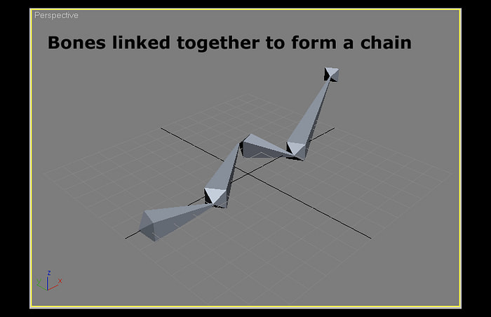
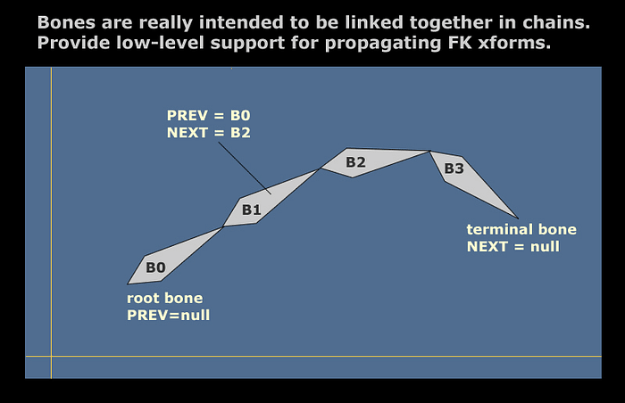
Bones are typically linked together in chains. The first bone in a chain is often called the root bone. In the arm example, the root of that chain is at the shoulder. The upper-arm bone is the first in the chain, and it is linked to the forearm bone. The root bone of a chain plays an important role as the only way to translate the entire chain in 2D or 3D space is to translate the root bone.
Here is an example of a bone chain from 3DS Max, a popular 3D software package from Autodesk.
Bone chains may also be linked to other bone chains. A common way to think about rigging an arm is a single chain for the upper/lower arm. That chain is linked to multiple single-bone chains in the hand. Each of those chains is linked to a two- or three-bone chain for each finger.
An organized collection of bone chains (and individual bones) that represent the entire skeleton of a single character is often called a character rig or a rig for short. The process of creating bones and organizing them into chains is called rigging.
Following is an example of very complex rig in 3DS Max that I developed in the mid-2000’s to animate a knight on a horse. This will give you some idea of the rigging capability provided in high-end 3D software.
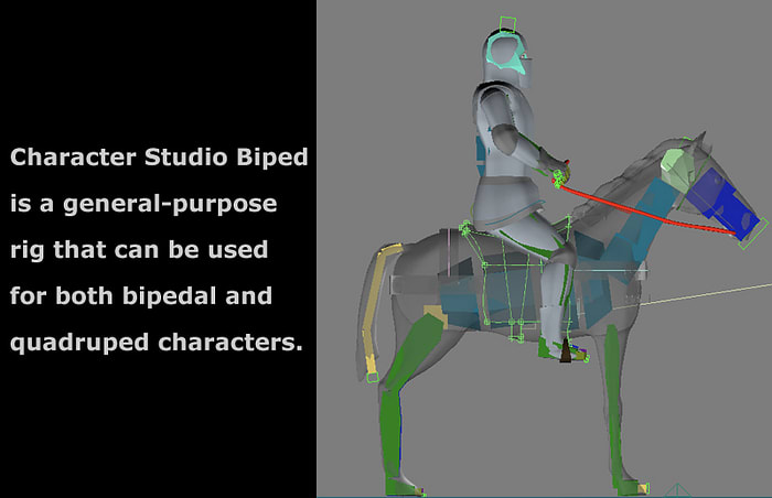
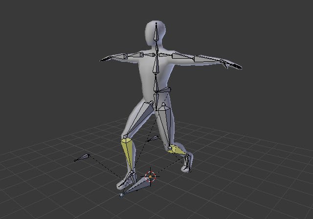
This particular setup employs two 3DS MAX Biped rigs, which is a special rigging system for bipedal characters. The character’s skin vertices (3D low-poly mesh) move as individual bones are transformed.
The manner in which bone chains respond to various transforms (translation and rotation, for example) is referred to as kinematics.
The study of kinematics in bone systems is generally broken into two categories, forward and inverse. Forward kinematics (FK) is relatively easy to understand, so we will begin there.
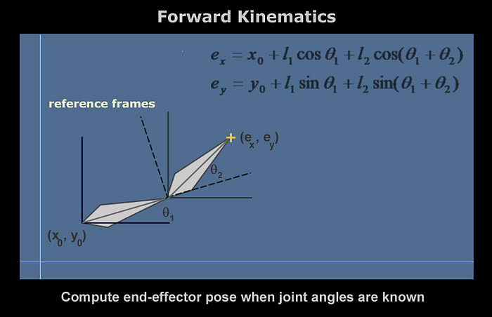
Forward Kinematics
If you hold your wrist and hand in a rigid posture, and then move your forearm around the elbow joint, you should make two observations.
- Your hand/fingers remain in the same relative posture; only their position changes in space.
- You are limited in how far the forearm can rotate (or twist) about the elbow joint.
The first observation introduces the fundamental tenant of forward kinematics; FK is mostly rotational in nature and rotation of a single bone in a chain propagates that transform forward in the chain. It is generally not possible to translate an arbitrary bone in the chain; translation is reserved for the root bone only. In that case, the translation is propagated forward to all other bones in the chain.
The second observation introduces the concept of rotational limits. Each bone is limited in how far it can rotate about a given axis.
A key feature of forward kinematics is that ‘solving’ for FK motion involves equations with closed-form solutions. That’s a fancy way of saying that the solution can be represented as a finite number of standard expressions or operations. Think of it as we could program the solution as a single block of code in a single pass through the equations.
And, if you’re thinking about bone chains as a linked list, then you are on the right track :)
Forward kinematics can be used to resolve many motions in a bone rig, but think about other motions such as a push-up.
Stand up and place your hand on a flat surface such as a desk. Lower your body while keeping the hand in the exact same orientation. Notice how the arm automatically moves to preserve its ‘chain’ and rotational limits at each joint. We might think of this as a situation where the terminal end of a bone chain is fixed (say the wrist bone in this case) and a transformation is computed that keeps the chain unbroken and preserves all rotational limits.
The term ‘transformation is computed’ is an entree into the second type of kinematic motion in a bone chain.
Inverse Kinematics
Now, we get to introduce some more terminology.
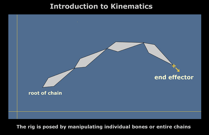
An ‘artificial’ point often call an end effector is added to the terminal joint of the chain. The end effector and the position of this terminal joint are identical when the bone is created and after any FK transform.
An end effector can be considered as the point on a bone chain to which other bones may be attached. We might attach a wrist bone to the end of an arm chain. Finger bones are then attached to the end effector of hand bones.
The end effector may be theoretically translated anywhere in space. Often, animation systems allow various physical ‘controllers’ to be attached to end effectors. When the end effector is moved, the bone system attempts to resolve a series of orientations that leaves the root bone fixed at its original position, maintains all bones within rotational limits, and moves the terminal joint as close as possible to the end effector.
This process attempts to resolve bone orientation from the terminal bone, backward, thus the term ‘inverse kinematics’ or IK. In order to programmatically support both FK and IK, a bone chain is implemented as a doubly-linked list.
One final consideration with end effectors is the concept of pinning. Let’s return to that push-up example, above. Based on prior discussion, we might think about IK as moving a wrist bone, and then propagating the chain backward towards the shoulder joint, forcing that joint to remain fixed.
The end-effector, however, might be pinned. This means that the end effector’s position is locked and the root bone of a chain is moved. That is how a push-up style motion is animated. The effector at the end of the arm chain (wrist joint) is pinned. The root bone of the arm chain (whose initial joint is the shoulder joint) is moved. This motion, in turn, activates an IK solution. (The current 2D library does not yet support pinned end effectors).
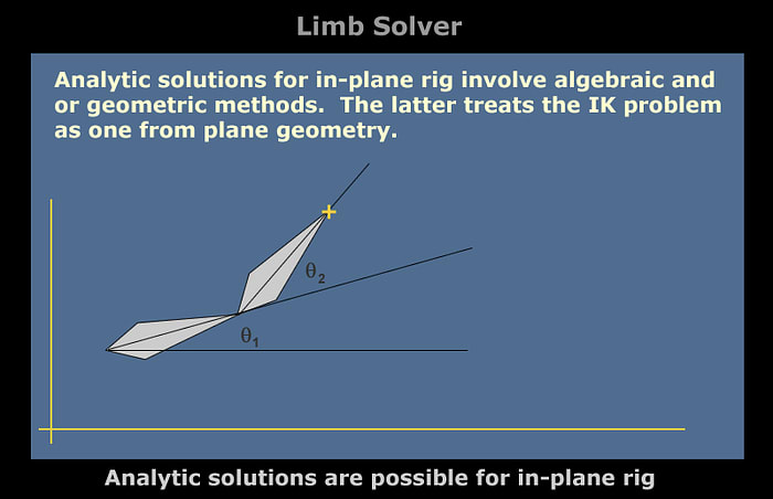
IK solutions are more complex and in general such solutions are not closed-form except for an in-plane, two-bone chain. This is sometimes called a ‘limb solver.’
General rigs, however, do not have closed-form IK solutions. The process of resolving the bone chain towards the end effector is iterative. This further complicates IK because convergence criteria may not be met in a fixed number of iterations. It is customary to place iteration limits on such solvers and algorithms constantly trade off qualitative aspects of the solution vs. performance.
A simple approach for the in-plane problem is to start at the terminal bone, then move back to the root bone while solving a series of FK problems. First, rotate and translate the terminal bone to place the terminal joint at the end effector location. This is a ‘target’ for that bone. Rotate and translate the previous bone to match the initial joint of the terminal bone. That is a ‘target’ for the next-to-last bone in the chain.
Then, work back to the root and see if it is possible to resolve the chain without violating a joint limit or breaking the chain. I learned this technique from a mechanical engineering professor in college who jokingly referred to it as ‘reverse forward kinematics.’ It can be considered as a simplification of another popular technique known as cyclic coordinate descent. While RFK is reasonable for 2D rigs, CCD is a much better option for general 3D rigs.
This RFK solver has been implemented for you in the current 2D library. For small movements of the end effector away and mostly unconstrained joint limits, it can almost always resolve the chain in a single iteration. If not, then the terminal bone is moved as close as possible to the end effector. That is considered a new end effector position and the RFK process proceeds through another iteration. This process continues until the chain is resolved or an iteration limit is met.
After the IK solution terminates, the end effector is moved back to the terminal joint.
In some cases, an animator might trigger simultaneous FK and IK resolution of a rig. Consider the simultaneous translation and rotation of a wrist bone. Rotation of the wrist bone is propagated forward to finger bones. The translation is also propagated forward to the root bone of each finger bones. This keeps the fingers from separating from the hand. Movement of the wrist bone, however, modifies the end effector of the arm chain. An IK solver is triggered to resolve the arm chain to ‘keep up’ with movements in the wrist. It is, of course, possible to move the wrist in such a manner that the arm chain can not be resolved. The rig never breaks, so the end effector separates to visually indicate to the animator that the limitations of the rig have been exceeded.
As there are many different algorithms for IK solution, it helps to make IK solvers pluggable. The current 2D library provides an interface for IK solvers that allows any solver satisfying the interface to be used to resolve IK motion in a chain.
Now, we have to means to resolve motion in bone chains. FK propagates transforms both forward in a chain and forward to anything linked to the end of the chain. IK generally solves backward from the terminal joint in a manner that preserves the root bone’s initial joint and satisfies all rotational joint limits, while trying to move the terminal joint as close as possible to an end effector.
So, what do we with do with it?
Skinning
This is the fun part, where we actually get to see something on a screen. In a 2D character system, we have a number of ways to visually represent simple cartoon characters. The process of ‘linking’ bones to influence character skins is called skinning.
1 — We can use the visual representation of bones themselves for suitably simplistic characters. Transforming a bone literally transforms the ‘skin’.
2 — A single sprite may be ‘linked’ to a bone, so that each bone in a rig has a one-to-one correspondence to a sprite. Moving and rotating a bone results in equivalent transforms for the sprite.
3 — Segmented skin. A single outline (such as a cubic Bezier spline) is applied to each bone in a chain. Moving and rotating a bone applies the transformations to the spline control points. This is great for worms or similar cartoon characters.
4 — Continuous skin. A single outline is applied to all bones in a chain.
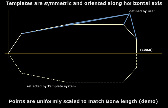
The bone template is an interesting concept that I have used in several projects. A template is simply a polynomial outline for a bone that is symmetric about the axis from initial to terminal joint.
A template is defined about the horizontal axis. Bone templates are generally defined from the origin to the point (100, 0). The actual bone may be drawn by applying translation, rotation, and non-uniform scaling to the template.
Now, very astute readers of this blog may think that they have heard about cubic Bezier splines. That’s because they have read this article :)
Cubic Bezier Splines With Angular 8 and PixiJS
We now have a perfect use-case for such a spline. Instead of a template, a small number of (symmetric) control points are created around each bone. A (closed) cubic Bezier spline is fit to those control points and used to draw an outline, which serves as our skin.
Just as in a 3D system where bone transforms modify control vertices of a character mesh, bone transforms in this skinning technique transform spline control points, which cause the outline to be redrawn.
I actually used this approach to animate a series of worm-like (segmented) characters in a Flash game. All characters were created and controlled dynamically.
Angular Demos
This article was largely intended to introduce terminology and concepts. The best way to learn the topic is to deconstruct and experiment with some existing code. Five Angular (version 9) demos are provided for you.
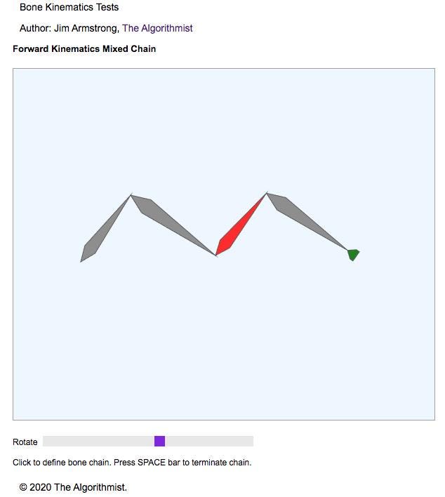
- FKChainTestComponent — Successive clicks in the drawing area generate bones. Use the space bar to terminate the chain. A ‘hand’ is forward-linked to the generated bone chain. Click on a bone to select that bone and then adjust the slider to rotate that bone. Note how FK is propagated forward to both subsequent bones in the chain as well as the ‘hand’.
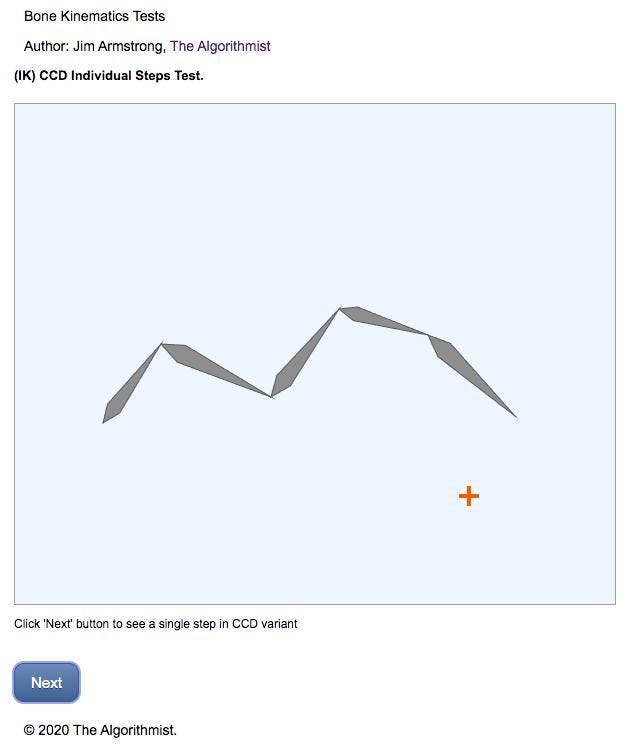
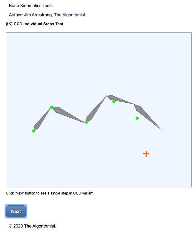
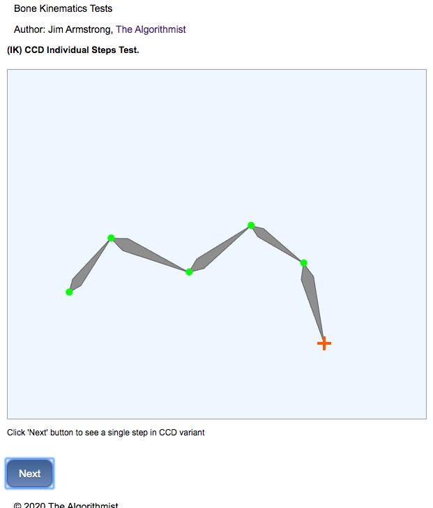
- CcdStepsComponent — One of the IK solvers provided with this code distribution is a modification of the classic cyclic coordinate descent algorithm (the RFK algorithm discussed above). It consists of a target phase and a solution phase. Each step of both phases can be interactively advanced (one step at a time) by clicking on a ‘Next’ button. This is a great learning tool!
- IkSolverTestComponent — Successive clicks in the drawing area generate bones and the space bar terminates the bone chain. A ‘hand’ is forward-linked to the generated bone chain. The ‘hand’ is linked to the end effector of the chain. Click and drag the hand to see the full IK solver in action. Note the effect of mixed FK/IK in a chain; the hand need not be repositioned at the end of the IK solve since it is forward-linked to the chain. Adjusting the terminal point of the chain from the IK solution automatically propagates to forward linkages.
- LimbSolverTestComponent — A 2-bone chain with joint (rotational) limits is generated. A visual representation of the end-effector is rendered. Drag the end effector to see how the limb solver resolves the bone orientation. Note that some configurations are completely infeasible because rotational limits on one of the bones would be violated. So, the chain remains in its current orientation until the end effector is moved to a feasible location. At that point, the rig appears to ‘snap’ into place.
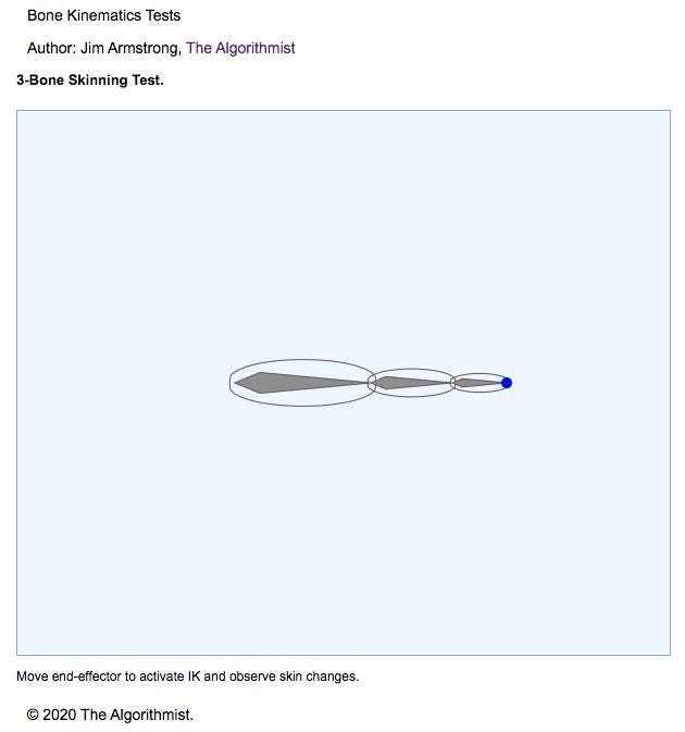
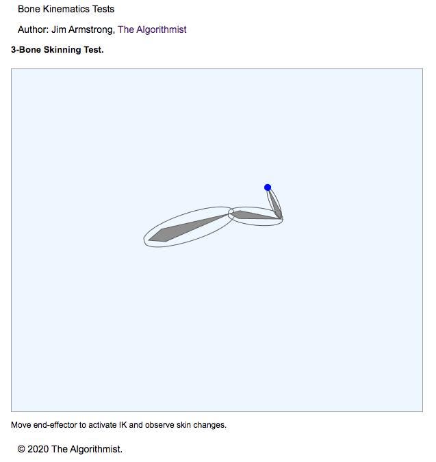
- SkinTestComponent — A 3-bone chain is created with a continuous, segmented skin for each bone. The skin is represented by a cubic Bezier spline. Both the bone and skin are rendered (although it is possible to render only the skin). Move the visual end effector to see both the IK solution a well as how the skin changes when bones are transformed.
Here are some screen shots of the demos in action.
Bone and skin displays are rendered into a Canvas (WebGL) using PixiJS. Structurally, each Canvas container is controlled by an Angular attribute directive. The directive exercises the Typescript rigging library.
On the subject of Angular, here is a note for beginners. The client rectangle for the containing DIV is necessary inside the directive to properly identify coordinates of mouse clicks. There are bound properties that are rendered into the DOM in the parent component (above the Canvas), so the parent’s DOM interpolation needs to be performed before computing the client rectangle inside the directive. Recall that lifecycle methods for a directive are executed after the equivalent methods in the host component. In many of my other demos, you may have seen the client rect. computed in a directive constructor. In this case, it is necessary to defer to the ngOnInit() handler.
Switching between demos is rather crude. Simply uncomment the component that is used to bootstrap the application in the main app module.
.
.
.
@NgModule({
  declarations: [
    FkChainTestComponent,
    CcdStepsComponent,
    BoneChainDirective,
    CcdStepsDirective,
    IkSolverTestComponent,
    IkSolverDirective,
    LimbSolverTestComponent,
    LimbSolverDirective,
    SkinTestComponent,
    SkinTestDirective
  ],
  imports: [
    BrowserModule
  ],
  providers: [],
  // Replace the bootstrap component to run other tests; crude but
quick :)
  bootstrap: [FkChainTestComponent]
  // bootstrap: [CcdStepsComponent]
  // bootstrap: [IkSolverTestComponent]
  // bootstrap: [LimbSolverTestComponent]
  // bootstrap: [SkinTestComponent]
})
export class AppModule { }
One final note is in order. The Typescript library includes a 2D representation of a complete Biped rig. While the ActionScript version of this code was tested, I did some substantial refactoring of the Typescript version. It has not yet been tested, so that code is completely experimental. If there is sufficient interest, I will expand the Typescript library to include more skinning options and provide better support for the 2D Biped rig.
I sincerely hope you enjoy working with the code and gain not only a better understanding of kinematics in character animation, but find some actual uses for these techniques in applications.
Good luck with your Angular efforts!
ng-conf: Join us for Reliable Web Summit
Come learn from community members and leaders the best ways to build reliable web applications, write quality code, choose scalable architectures, and create effective automated tests. Powered by ng-conf, join us for the Reliable Web Summit this August 26th & 27th, 2021.
https://reliablewebsummit.com/

Top comments (0)