
Preamble:
This space will be utilized to synthesize my notes and help improve my learning process while I study for the CompTIA Network+ N10-009 certification exam. Please follow along for more Network+ notes and feel free to ask any questions or, if I get something wrong, offer suggestions to correct any mistakes.
The Open Systems Interconnection (OSI) model breaks the data communications process into 7 distinct layers. It was created to promote understanding of how components in a network system work together. Being able to understand what each layer is responsible for will be helpful when talking with other networking professionals as well as troubleshooting network issues.
The OSI model is not a standard or a specification; it serves as a functional guideline for designing network protocols, software, and appliances and for troubleshooting networks.
NOTE: When a message is sent from one node to another, it travels down the stack of layers on the sending node, reaches the receiving node through the transmission media, and then passes up the stack on that node. At each level (except the Physical layer), the sending node adds a header to the data payload, forming a data chunk called a protocol data unit (PDU).
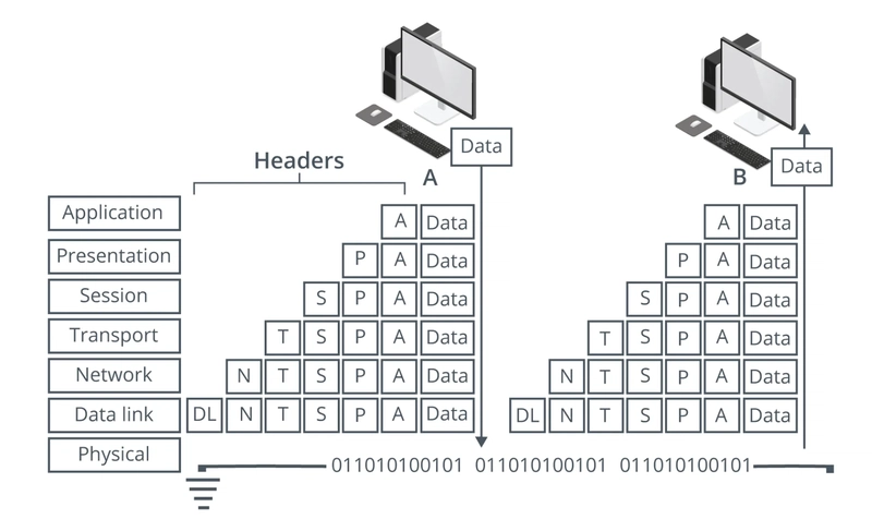 Example of encapsulation and decapsulation from Computer A to Computer B
Open Systems Interconnection Model
Below are the layers of the OSI model and a brief explanation of what each layer does
- Application: Provides network services directly to end-user applications (e.g., web browsers, email clients).
- Presentation: Handles data formatting, encryption, and translation to ensure that applications can understand the data.
- Session: Establishes, manages, and terminates communication sessions between applications.
- Transport: Provides reliable or unreliable delivery of data between applications, including error checking and flow control.
- Network: Provides logical addressing (IP addresses) and routing of data packets across networks.
- Data-Link: Provides physical addressing (MAC addresses), error detection, and framing of data within a local network segment.
- Physical: Defines the physical characteristics of the network, including cables, connectors, and signaling.
We’ll start from the bottom (Layer 1) of the OSI model and move up.
Physical Layer (Layer 1)
The physical layer can be cabled or wireless.
Cabled (bounded media) connection sends a physical signal down the wire between nodes. This can be accomplished utilizing copper or fiber optic cables.
Wireless connection (unbounded media) does something similar to a cabled connection except it utilizes microwave radio signals at specific frequencies.
The Physical layer also specifies the following
- Physical Topology: Layout of the nodes and links established by the transmission (wired or wireless) media. An area of a larger network is called a segment. Segments are where all nodes share access to the same media. Networks are generally divided into segments to cope with physical limitations of the network media used. to help improve performance of the network or to improve network security.
- Physical Interfaces: These are the mechanical specifications of the network medium. For cabled media this is referring to the construction of the cable itself, the interface or connector of the cable and the number of pins used in the cable. For wireless media this refers to the radio transceiver and antenna specifications. Ex: RJ45 (copper), LC and SC (Fiber)
- Signaling: The process of transmitting and receiving encoded data over the network medium. A modulation scheme describes how electrical, light, or radio signals represent bits. Timing and synchronization schemes ensure senders and receivers can identify groups of signals as a chunk or frame of data.
Devices that operate on the Physical Layer
- Transceiver: Part of the network interface that sends and receives signals over a network
- Repeater: Device that amplifies the electronic signal and extend the maximum allowable range for that media type.
- Hub: A multi-port repeater that broadcasts received signals to all connected devices. It operates in a half-duplex mode, meaning devices cannot send and receive simultaneously, leading to potential collisions. A hub creates a single collision domain. NOTE: This is different from a Network Switch which works at the Layer 2 Data-Link Layer.
- Media Converter: Device that converts from one physical media to another. Example would be to convert from Optical Fiber to Copper.
- Cables:
- Copper: Cat5e, Cat6, Cat6a (Used for Ethernet)
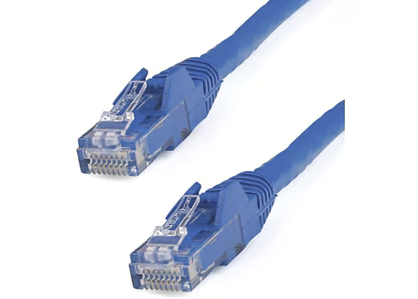 CAT 6 Ethernet Cable
- Fiber: Single-mode (long distance), multi-mode (short distance)
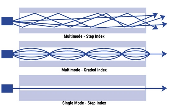
Visualization of Single Mode and Multi-Mode Fiber Cables
I will leave it there for today's Network+ notes. Thanks for joining me and I hope you learned a little about how important the physical layer is not only for knowing how networks work, but also to help you on your journey with troubleshoot network related issues. Join me next time to learn about Layer 2, the Data-Link layer.

Top comments (0)