In the development of electronic devices, we often encounter the design of our own hardware, but in the early stages of learning, it is better to buy a ready-made development board that already provides the basic things for the proper operation of the microcontroller. Although I will be using the ready-made Arduino hardware and Arduino development environment in the initial programming texts, it is necessary to understand the basics of designing hardware, which I will explain in more detail. My generation was not as lucky as today's "Facebook" kids because there was no Arduino and we could only buy a microcontroller and programmer. We designed the hardware independently, but we were not familiar with the details to pay attention to, so our devices worked in such an unstable environment. Turning on and off an LED will bore an average programmer after 5 minutes, and there is an immediate need to connect the microcontroller to various sensors, LCD, keyboards, and designing devices that have a specific purpose. Therefore, proper hardware design is extremely important before programming because if there are errors in the device's operation, it is often difficult to distinguish whether it is a hardware or software error. Hardware design is identical for all microcontrollers and consists of the three most important rules for stable microcontroller operation:
• Stable power supply voltage
• Stable operating frequency
• Stable microcontroller reset line
It is necessary to remember these items because they are extremely important in hardware design and can often give us a headache if we do not adhere to them. The slightest mistake in them can result in "strange" microcontroller behavior that sometimes stops working or performs some magic that we cannot explain logically. As an example of hardware design, I will use the ATMEGA8A microcontroller.
Stable power supply voltage
We often think that connecting a microcontroller to the power supply voltage defined in the technical documentation is sufficient, but in practice, it simply won't be enough. The stability of the power supply voltage is one of the most important requirements for any microcontroller, and if the voltage is not stable, the microcontroller may execute a program instruction incorrectly, causing our device to freeze. The microcontroller is not an analog component with a constant energy consumption, but rather, when executing assembly instructions at the clock edges, there is a need for a large power consumption that lasts only a few ns (nanoseconds). Therefore, in hardware design, it is necessary to provide fast and always available energy that the microcontroller can use. Such a fast need for current cannot be delivered to the microcontroller via long power lines, so the main source should be a capacitor. There is a golden rule that ensures fast and always available energy for a stable microcontroller voltage: "Place a 100nF capacitor between GND and VCC as close as possible to each microcontroller power pin." It is good practice, but not necessary, to place a coil in series with the microcontroller power supply to reduce interference on the power supply lines caused by the microcontroller's fast and short current needs. The resistance of the coil must be low enough to ensure that the microcontroller's power supply voltage does not drop to a critical level. Note that larger microcontrollers often have more power pins, so they all need to be properly connected to the power supply voltage. Most AVR microcontrollers have an implemented analog-to-digital converter (ADC) that has special inputs for the power supply voltage and reference voltage, so AVCC and AREF need to be connected to 5V, and AGND to GND. The correct layout of the elements in the microcontroller power circuit is shown in the picture.

The operating voltage of a microcontroller is always specified in the technical documentation, but it is often dependent on the microcontroller's operating speed. Most AVR microcontrollers specify a voltage range of 4.5-5.5V in the technical documentation when the microcontroller is operating at maximum speed. The technical documentation often lists the maximum operating speeds for the same microcontroller (e.g. 0-8 MHz @ 2.7-5.5V, 0-16 MHz @ 4.5-5.5V), so AVR microcontrollers can often operate at lower voltages at lower speeds. The ATMEGA8A can operate at a voltage range of 2.7-5.5V, but it is most commonly used with a 5V power supply. In the design of the microcontroller hardware, it is also necessary to design voltage stabilization for 5V, which is already done on development boards. Do not be fooled into thinking that voltage stability can be measured with a simple voltmeter, as an oscilloscope is still required for this, because the problem lies in the microcontroller's operating speed. If the ATMEGA8A can operate at 16 MHz, it is easy to calculate how often the AVR will execute one assembly instruction:
T=1/F=1/16000000=62,5ns (0.000 000 062 500 s)
So, the AVR will execute one assembly instruction in just 62.5 ns (nanoseconds). In the event that the voltage on the microcontroller drops below the allowed level for an extremely short period of time (e.g. 500ns), there is a high probability that the microcontroller will execute the wrong instruction. A wrongly executed instruction is like winning the lottery and may not necessarily lead to a program crash. Perhaps the AVR was executing an instruction that was not very important for the program's further operation (e.g. adding 2 numbers whose result is room temperature, which will not crash the program if calculated as 1000 °C by mistake). The AVR microcontroller has protection against low operating voltage, but unfortunately, the only solution is to reset and restart the program. The lottery is not what you want to gamble on in development, and it is definitely better to design hardware that has a safe and stable operating voltage. For a 5V voltage stabilizer, you can start with LM7805, but be sure to rely on the voltage stabilizer's technical documentation and implement the recommended input and output capacitors in the hardware.
Stable operating frequency
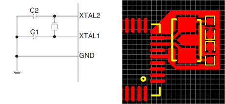
In addition to the operating voltage, it is necessary to ensure a stable operating frequency for proper operation of the microcontroller, which affects the speed of instruction execution. AVR microcontrollers have an internal oscillator implemented, so no external components are needed for microcontroller operation. The technical documentation states that the ATMEGA8A is supplied with an internal oscillator set to a frequency of 1 MHz. If the internal oscillator of the controller is used for the clock, the XTAL1 and XTAL2 lines are not connected. In device development, the internal oscillator is rarely used due to its tolerance. An external crystal oscillator is much more accurate than an internal oscillator and is therefore used much more often. The only drawbacks of an external crystal oscillator are the increased size and cost of the device. The diagram and circuit board for connecting an external crystal oscillator are shown in the figure.
Stable Reset Line of Microcontroller
The reset line of a microcontroller is used to restart the program, and although it may seem harmless, it can be a potential source of difficult-to-solve problems. ATMEGA8A has 4 sources of reset: Power-on Reset, External Reset, Watchdog Reset, and Brown-out Reset. Only 2 sources of reset are included in the delivered AVR microcontroller: Power-on Reset and External Reset, so I will explain them in more detail.
Power-on Reset is used to reset the microcontroller when we first connect it to the power supply, and if we have designed a stable power supply, we will not have any problems with it. It will correctly start the program from the initial address when the power supply voltage exceeds the lower limit of 2.3V, and as long as the power supply voltage is higher than 2.3V, the microcontroller will execute the program correctly.
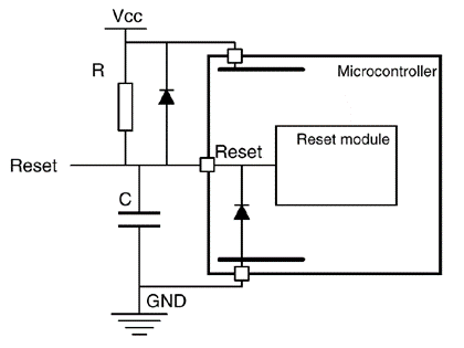
External Reset is a pin of the microcontroller that will reset the microcontroller when the voltage on it is lower than 0.9V for at least 1.5 microseconds. If we do not connect the external reset pin, it would often fall to 0V due to external interference and unnecessarily reset the microcontroller. To keep the external reset pin above 0.9V, we connect it via a 4.7 kOhm resistor to the power supply voltage (5V) and place a 100nF capacitor towards GND that does not allow sudden and rapid changes in the reset line caused by external interference in the hardware. The correct connection of the reset line of the AVR microcontroller is shown in the figure.
The following text will present a complete design of the schematic and hardware for the ATMEGA8A MCU that you can use as a reference when designing your own devices.

Top comments (0)
Some comments may only be visible to logged-in visitors. Sign in to view all comments.