
In today's post, I wanted to talk about a program that many engineering companies use for 3D design: CATIA V5. It will be a short introduction in which we will cover: The user interface, the start menu and the most used and basic modules in CATIA V5. So, let's get started!
Working interface
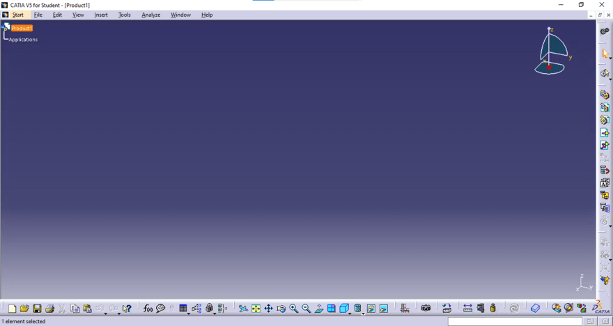
When we first open CATIA V5, the first thing we will see is:

It may also happen that you see this window:
Don't worry, as it has just opened an assembly design type. Close it with the x button on the top right side (careful not to close the program!).

As we can see in the first image, we can find different areas in the working interface:
- Dropdown menu area: All the dropdown menus are located here, with many diverse options.
- Toolbar areas: This is where all the buttons and options related to the design will appear when we open a module. We can customize these areas by moving the toolbars (we may leave them in the middle of the graphical representation area) and adding or eliminating buttons and options.
- Graphical representation area: This is where our 3D design (or the 2D drawings) will appear and where we will make all the changes to the part or assembly.
- Message area: Where all the messages and tips will appear. For example, if you select a geometry modification operation, CATIA will tell you in this window to choose what feature of the part you want to modify.
- Command introduction area: You can write different commands instead of clicking buttons in the toolbar areas.
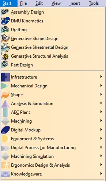
The start menu
In this dropdown menu, we can access all the modules available in CATIA V5, ordered in different categories, depending on the licence that we have installed.
Most used modules in mechanical design
The modules are also known as Workbenches, and each has different options to work with parts in different ways, depending on what we want to do.
We will now discover the most used workbenches in mechanical design and shape groups.
Mechanical design group
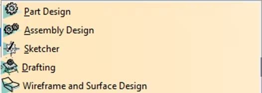
Part Design: Used for designing solid parts. In this workbench, we can create any solid geometry. It is the most used module in design.
Assembly Design: We use this module to manage different groups made of diverse parts. With this workbench, we can create and join many pieces to create groups. It is a crucial module for creating mechanisms.
Sketcher: We use this one to create drawings. We can make different drawings to prepare the shapes for future parts (with dots, lines, curves, etc.). It is the most fundamental module, as it is necessary to start with any design. It is the first module people always learn.
Drafting: We use this to create manufacturing drawings of a 3D geometry.
Wireframe and Surface Design: This is a simple module for surface design. It is not very used, as there is a much better option for surface design: The Generative Shape Design module.
Shape group

Generative Shape Design: This is the main module for creating different surface designs. You will be able to design any shape based on surfaces.
Conclusion
CATIA V5 is a powerful tool in 3D design, and I consider it the best tool in the market for this job, especially when we talk about surface design.
The downside is that it is also a very complex program, and mastering all its modules is almost impossible. But I hope that, with this small intro to the software, now you know a bit more about what you can create with this marvellous design tool.
The possibilities it offers related to CAD design are huge!

Top comments (0)