1. Introduction
The project is a simple example showcasing a quick way to set up a STM32Cube project as a USB CDC Host capable of communicating with the BleuIO Dongle.
When a BleuIO Dongle is connected to the Nucleo boards USB port the STM32 will recognize it. It will then accept 3 different inputs from the UART and send one of 3 preprogrammed commands to the BleuIO Dongle based on the input.
The commands that are used in this example are:
- ATI (Dongle Information)
- AT+ADVSTART (Starts Advertising)
- AT+ADVSTOP (Stops Advertising)
We have used a STM32 Nucleo-144 development board with STM32H743ZI MCU (STM32H743ZI micro mbed-Enabled Development Nucleo-144 series ARM® Cortex®-M7 MCU 32-Bit Embedded Evaluation Board) for this example.
If you want to use another setup you will have to make sure it support USB Host and beware that the GPIO setup might be different and may need to be reconfigured in the .ioc file.
2. About the Code
You can get project HERE
This project based on a new STM32 project with these changes in the .ioc file:
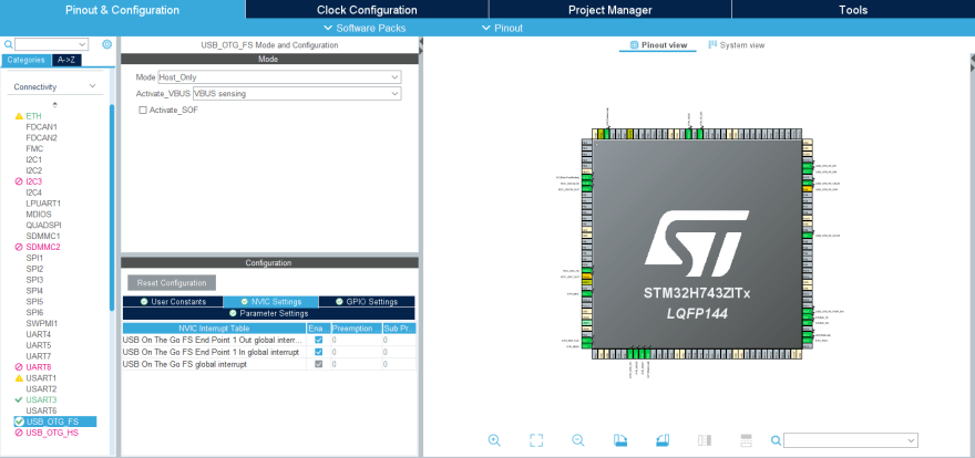
Under 'Connectivity' the 'USB_OTG_FS'-mode is changed to Host_Only and in the NVIC Settings all global interrupts are enabled.
And under 'Middleware' the 'USB_HOST'- 'Class for FS IP' is set to 'Communication Host Class (Virtual Port Com)'.

To make sure the host would recognize when the bootloader is done and the BleuIO firmware is running this was added in the USBH_UserProcess function in 'usb_host.c' (found under 'USB_HOST' -> 'App' folder):
static void USBH_UserProcess  (USBH_HandleTypeDef *phost, uint8_t id)
{
  /* USER CODE BEGIN CALL_BACK_1 */
  switch(id)
  {
  case HOST_USER_SELECT_CONFIGURATION:
  break;

  case HOST_USER_DISCONNECTION:
  Appli_state = APPLICATION_DISCONNECT;
  isBleuIOReady = false;

  // Turn on Red LED, turn off Green and Yellow LED
  HAL_GPIO_WritePin(GPIOB, GPIO_PIN_0, GPIO_PIN_RESET);
  HAL_GPIO_WritePin(GPIOE, GPIO_PIN_1, GPIO_PIN_RESET);
  HAL_GPIO_WritePin(GPIOB, GPIO_PIN_14, GPIO_PIN_SET);
  break;

  case HOST_USER_CLASS_ACTIVE:
  Appli_state = APPLICATION_READY;
  // Check if BleuIO firmware is running
  // (idProduct:0x6001 = bootloader, idProduct:0x6002 = bleuio fw)
  if(phost->device.DevDesc.idProduct == 0x6002)
  {
      isBleuIOReady = true;
      // Sends message to uart that BleuIO is connected and ready
      HAL_UART_Transmit(&huart3, (uint8_t*)BLEUIO_READY, strlen(BLEUIO_READY), HAL_MAX_DELAY);

      // Turn on Green LED, turn off Yellow and Red LED
      HAL_GPIO_WritePin(GPIOB, GPIO_PIN_0, GPIO_PIN_SET);
      HAL_GPIO_WritePin(GPIOE, GPIO_PIN_1, GPIO_PIN_RESET);
      HAL_GPIO_WritePin(GPIOB, GPIO_PIN_14, GPIO_PIN_RESET);

      // Start receiving from usb
      USBH_CDC_Receive(&hUsbHostFS, CDC_RX_Buffer, RX_BUFF_SIZE);
  }
  break;

  case HOST_USER_CONNECTION:
  Appli_state = APPLICATION_START;
  isBleuIOReady = false;
  // Turn on Yellow LED, turn off Green and Red LED
  HAL_GPIO_WritePin(GPIOB, GPIO_PIN_0, GPIO_PIN_RESET);
  HAL_GPIO_WritePin(GPIOE, GPIO_PIN_1, GPIO_PIN_SET);
  HAL_GPIO_WritePin(GPIOB, GPIO_PIN_14, GPIO_PIN_RESET);
  break;

  default:
  break;
  }
  /* USER CODE END CALL_BACK_1 */
}
The Green, Red and Yellow LEDs on the Nucleo board is also setup to change based on the connection status.
Red = Disconnnected.
Yellow = Connecting.
Green = Connected.
An external variable bool isBleuIOReady is also set so the status of the dongle is accessible from main.c.
Once the BleuIO dongle is confirmed to be connected the USBH_CDC_Receive function is run to start reciving data from the USB CDC.
The USBH_CDC_ReceiveCallback also needs to be implemented:
void USBH_CDC_ReceiveCallback(USBH_HandleTypeDef *phost)
{
    if(phost == &hUsbHostFS)
    {
        // Handles the data recived from the USB CDC host, here just printing it out to UART
        rx_size = USBH_CDC_GetLastReceivedDataSize(phost);
        HAL_UART_Transmit(&huart3, CDC_RX_Buffer, rx_size, HAL_MAX_DELAY);

        // Reset buffer and restart the callback function to receive more data
        memset(CDC_RX_Buffer,0,RX_BUFF_SIZE);
        USBH_CDC_Receive(phost, CDC_RX_Buffer, RX_BUFF_SIZE);
    }

    return;
}
In this example the recieved data is just echoed to the UART.
To send data to the Dongle the USBH_CDC_Transmit function is used.
In this example UART input is used to send different commands.
For this purpose a wrapper function has been created that can be accessed from main.c:
/**
  * @brief Simple function that takes a string and transmit it to the dongle
  * @retval None
  */
void writeToDongle(uint8_t * cmd)
{
    USBH_CDC_Transmit(&hUsbHostFS, cmd, strlen((char *)cmd));
}
In main.c HAL_UART_RxCpltCallback is implemented to recieve input from Uart and a simple UART input handler:
void HAL_UART_RxCpltCallback(UART_HandleTypeDef *UartHandle)
{
    if(UartHandle == &huart3)
    {
        RX_value = (int)aRxBuffer[0];
        uartStatus = UART_RX_NONE;

        switch(RX_value)
        {
            case UART_RX_0:
            {
                uartStatus = UART_RX_0;
                break;
            }
            case UART_RX_1:
            {
                uartStatus = UART_RX_1;
                break;
            }
            case UART_RX_2:
            {
                uartStatus = UART_RX_2;
                break;
            }
            default:
            {
                uartStatus = UART_RX_NONE;
                break;
            }
        }
        // Resets uart recieve interrupt mode
        HAL_UART_Receive_IT(&huart3, (uint8_t *)aRxBuffer, RXBUFFERSIZE);
    }
}


/**
  * @brief Simple uart input handler
  * @retval None
  */
void handleUartInput(UARTCommandTypeDef cmd)
{
    switch(cmd)
    {
        case UART_RX_0:
        {
            // 0
            uart_buf_len = sprintf(uart_tx_buf, "\r\n(0 pressed)\r\n");
            HAL_UART_Transmit(&huart3, (uint8_t *)uart_tx_buf, uart_buf_len, HAL_MAX_DELAY);
            if(isBleuIOReady)
            {
                writeToDongle((uint8_t*)DONGLE_CMD_ATI);
            } else
            {
                uart_buf_len = sprintf(uart_tx_buf, BLEUIO_NOT_READY_MSG);
                HAL_UART_Transmit(&huart3, (uint8_t *)uart_tx_buf, uart_buf_len, HAL_MAX_DELAY);
            }
            uartStatus = UART_RX_NONE;
            break;
        }
        case UART_RX_1:
        {
            // 1
            uart_buf_len = sprintf(uart_tx_buf, "\r\n(1 pressed)\r\n");
            HAL_UART_Transmit(&huart3, (uint8_t *)uart_tx_buf, uart_buf_len, HAL_MAX_DELAY);
            if(isBleuIOReady)
            {
                writeToDongle((uint8_t*)DONGLE_CMD_AT_ADVSTART);
            } else
            {
                uart_buf_len = sprintf(uart_tx_buf, BLEUIO_NOT_READY_MSG);
                HAL_UART_Transmit(&huart3, (uint8_t *)uart_tx_buf, uart_buf_len, HAL_MAX_DELAY);
            }
            uartStatus = UART_RX_NONE;
            break;
        }
        case UART_RX_2:
        {
            // 2
            uart_buf_len = sprintf(uart_tx_buf, "\r\n(2 pressed)\r\n");
            HAL_UART_Transmit(&huart3, (uint8_t *)uart_tx_buf, uart_buf_len, HAL_MAX_DELAY);
            if(isBleuIOReady)
            {
                writeToDongle((uint8_t*)DONGLE_CMD_AT_ADVSTOP);
            } else
            {
                uart_buf_len = sprintf(uart_tx_buf, BLEUIO_NOT_READY_MSG);
                HAL_UART_Transmit(&huart3, (uint8_t *)uart_tx_buf, uart_buf_len, HAL_MAX_DELAY);
            }
            uartStatus = UART_RX_NONE;
            break;
        }
        case UART_RX_NONE:
        {
            break;
        }
        default:
        {
            uartStatus = UART_RX_NONE;
            break;
        }
    }
}
The handleUartInput() handles the inputs 0, 1 and 2 and maps each to a certain Dongle commands. The handler is then put inside the main loop.
  /* Infinite loop */
  /* USER CODE BEGIN WHILE */
  while (1)
  {
    /* USER CODE END WHILE */
    MX_USB_HOST_Process();
    /* USER CODE BEGIN 3 */
    // Simple handler for uart input
    handleUartInput(uartStatus);
  }
  /* USER CODE END 3 */
3. Using the example project
3.1 What you will need
- A BleuIO dongle (https://www.bleuio.com/)
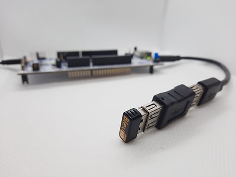
- A board with a STM32 Microcontroller with a USB port. (A Nucleo-144 development board: NUCLEO-H743ZI2, was used developing this example. (https://www.st.com/en/evaluation-tools/nucleo-h743zi.html) To connect the dongle to the Nucleo board a "USB A to Micro USB B"-cable with a USB A female-to-female adapter can be used.)
- STM32CubeIDE (https://www.st.com/en/development-tools/stm32cubeide.html)
4. How to setup project
4.1 Downloading the project from GitHub
Get project HERE
Either clone the project, or download it as a zip file and unzip it, into your STM32CubeIDE workspace.
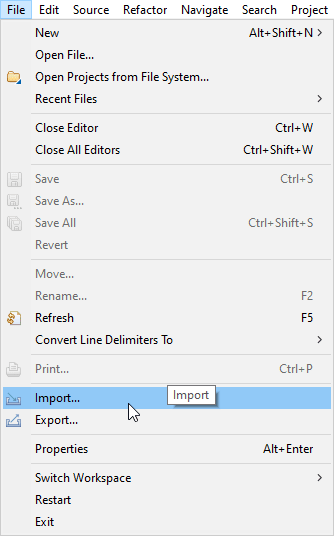
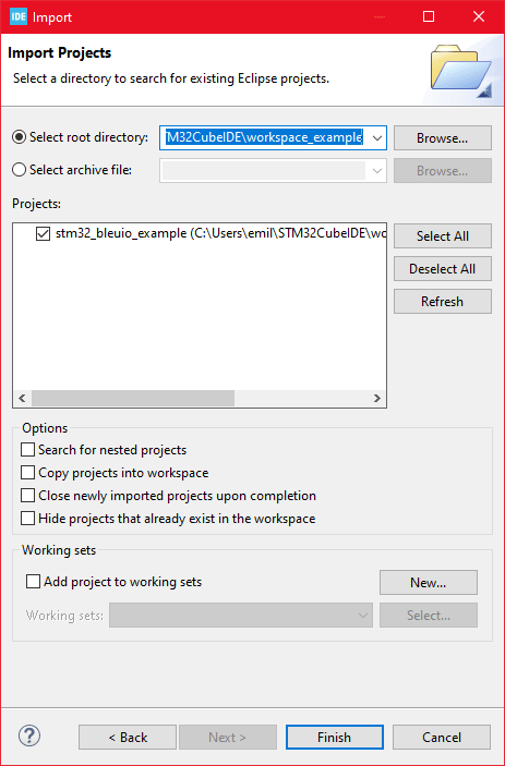
4.2 Importing as an Existing Project
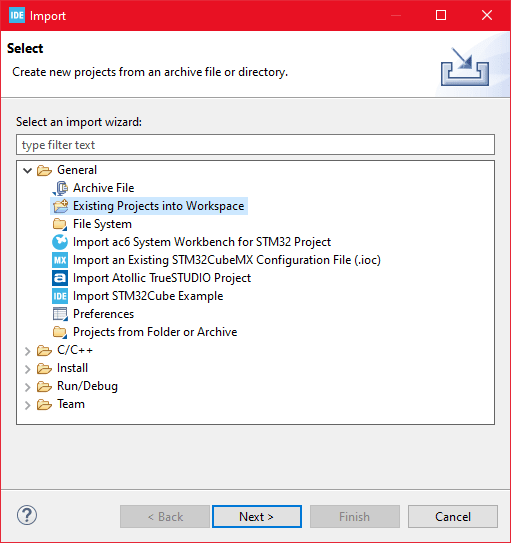
Then choose General>Existing Projects into Workspace then click 'Next >'
- Make sure you've choosen your workspace in 'Select root directory:'
- You should see the project "stm32_bleuio_example", check it and click 'Finish'.
5. Running the example
- In STMCubeIDE click the hammer icon to build the project.
- Open up the 'STMicroelectronics STLink Viritual COM Port' with a serial terminal emulation program like TeraTerm, Putty or CoolTerm.
Serial port Setup:
Baudrate: 115200
Data Bits: 8
Parity: None
Stop Bits: 1
Flow Control: None
In STMCubeIDE click the green play button to flash and run it on your board. The first time you click it the 'Run Configuration' window will appear. You can just leave it as is and click run.
Connect the BleuIO Dongle.
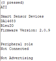
Dongle response will be printed to UART.





Top comments (0)