
This is the part 3 of the series "Building networks from A to Z", I strongly suggest that you read the two previous parts before reading this one, as we will be using knowledge from them. Thank you.
Now that we have seen the Physical layer, it is time to discover Data link. This is the first abstraction layer of the OSI model, and is part of layer 1 of TCP/IP model for reasons that we will see later on this post.
I would, first, like to talk about Network topology. The architecture of networks isn't quite arbitrary, and it is often designed by the layer 2 protocol, the Data link.
This layer is very interesting and we can see it everywhere, not even on Internet networks, but even on Bluetooth, where addressing is exactly the same. But first, let's talk about building our local network !
Network terminology
Before going further, I would like to speak about networks terminology. We have used some acronyms to qualify different networks, and it is something you might want to know when talking to a net guy (nerd).
From tiniest network to biggest :
- PAN (Personal Area Network) : mostly used for 2-devices communication, for example, USB is a wired PAN, Bluetooth is a wireless PAN (WPAN). Its range is usually a few meters (1 or 2, not much more). PAN networks do not need network infrastructure !
- LAN (Local Area Network) : the network we have at home ! Usually composed of a few devices, it is centered around a router and a switch. A data link wildly used for LAN is Ethernet (wired) and WLAN (802.11 "Wi-Fi"), they both use MAC addresses (as well as Bluetooth), which we will be discussing later.
- MAN (Metropolitan Area Network) : a network slightly bigger than LAN, used in cities and universities. Generally used when multiple LAN are used by the same entity, older protocols like ATM and SDDI were used for its purpose, now replaced by Gigabit and 10-Gigabit Ethernet as well as MPLS (which will be discussed at the VERY end of the series!). Structured around multiple routers and multiple switches, both in the same organization and composing the backbone of an Intranet ("network of networks of an organization" - connecting multiple networks of the same entity).
- RAN (Regional Area Network) : usually refers to broadcasting TV or radio, using VHF (Very High Frequencies) and UHF (Ultra High Frequencies) using OFDMA multiplexing. We will very probably not discuss those technologies at all, can be interesting in a Telecommunications series (maybe one day?).
- WAN (Wide Area Network) : the biggest of them all, the best example ? The Internet is a WAN, connects at the same time RAN, MAN and LAN together to form the WAN.
Here is a quick illustration :

With that being said, we skip network terminology and basic architecture to enter topology related to Data link protocols !
Data link protocols and network topologies
Network engineers and administrators have known multiple protocols during many years, many companies were trying to sell their own implementation of a Data link protocol, but, thankfully, this trend converged into adopting Ethernet as a whole. We will discuss how the Data link protocols are responsible for Network topology and how it evoluted during time !
1. The Ring networks
This is the first network topology that we will discuss. The main property of a ring network is that every computer is connected to the previous one but also the next. A little illustration :

The most known protocol for ring networks as LAN is Token Ring, developed by IBM in the mid-80s. The principle of Token Ring is that in order to communicate, the computer must have the token, which distributes the communication time. A big advantage of this technology is that we have no collision whatsoever, but the efficient bandwidth is majorly reduced when we add more and more computers, as we divide the communication time. As far as other Data link protocols by the time, infrastructure was only sold by the companies which have the patent of the protocol, and they were controlling the licensing price.
Another well-known ring network is FDDI (Fiber Distributed Data Interface), often used to connect many LANs together in order to create a MAN. FDDI uses fiber cables to have a 200km+ range and 100Mbps speed, two routers were then connected to each other using 4 fibers (SM - Single-mode). 2 fibers were used for full-duplex in one way and the 2 others for the other way. This architecture is really stable as it is given a natural redundant path.
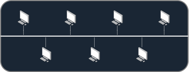
2. The Bus networks
Bus network consist in having all the computers on a single medium, which is known as a "bus" in IT. It is not really used nowadays, but still has some advantages, for example the cost of the overall network, the simplicity of connecting devices to it. However, if the cable serving the bus is cut or broken, the whole network fails, which is a critical criteria to avoid when building networks. Here is an illustration if you don't see what it is :
3. The Mesh networks
Mesh networks are not really known from the "outer-IT world" but are quite common. Its principle is to have every device of the network connected to all the others. Here is a little illustration :

It is mostly used in Wi-Fi where in some networks, all the wireless routers (or APs - Access Points) are connected in a mesh network. A derivate example to the Mesh networks are the connections between neighbor eNodeB (antennas in LTE and LTE-Advance networks - Access networks, also discussed in a future post), that for sake of "handover" (the fact is switching antenna when moving without losing signal) are connected to the neighbors and handing connections to them via a protocol that's called X2.
4. The Star networks
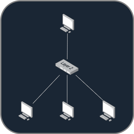
Star networks are by far the most common ones. The principle is to have every device of the network connected to a central point, either a switch or a hub. We will be discussing the differences between them at the end of this section !
So you get it, Ethernet is the most famous protocol that describes a Star network. As usual, here is an illustration of a Star network :

This architecture is the most used one because Ethernet was only free, and as noted above, it wasn't the case of all Data link protocol. Ethernet was quite a poor protocol compared to Token Ring for example, it has a high collision factor and requires a lot of cables to work. In IT, often time, the quality of the product isn't the most important factor, but the cost really is relevant.
Ethernet has been fixed many times in hopes to reduce collisions, and it works as well as required to run it throughout the world nowadays !
Each Data link protocol has its own implementation of the MAC addressing system, but the Ethernet one is the most famous, obviously.
A MAC address is an unique physical address, linked to a Network card (NIC) and determined during the manufacturing process. For Ethernet, each MAC address is composed of 6 bytes, quite always represented in hexadecimal, like that ee-f6-ab-d7-cd-07 (MS-DOS approach) or like that ee:f6:ab:d7:cd:07, sometimes also with a ..
The hub is used to concentrate all the data in a single point and redistribute it at all the connected devices. Here is a quick illustration of the hub principle :
A hub is a quite dumb device. It doesn't really care about MAC addresses. With the hub broadcasting data, you can imagine that the other PCs trying to emit while the upper one is still communicating can cause problems. That's why Ethernet logical topology, opposed to physical, is a Bus network, because the media is shared between hosts.
Opposed to the hub, the switch will be reading the destination MAC address from the Ethernet header and sending the data only to the PC concerned. The other devices will not even be able to see the data.
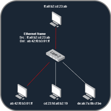
Ethernet is called a switching protocol because of this property, and also the fact that it would be totally unusable without this addon.
Although, even if collision is fixed with unicast (PC-to-PC communication, one device talks to one another), it is still a big issue while broadcasting. Indeed, Ethernet supports broadcasting to all PCs using a specific MAC address, ff:ff:ff:ff:ff:ff (which corresponds to all bits value being 1). The switch will then take the broadcasting request and redistribute it as a hub, to all hosts connected. This is called the broadcast domain. It might not be an issue on little networks, but when connecting switches to another switches, you can easily reach large amounts of hosts.
One solution to this problem has been CSMA/CD (Carrier Sense Multiple Access with Collision Detection), that will be listening to the media to determine if another host is talking, when not, it will emit the data it has to. However, if a collision is detected, the host will stay silent for a random period of time (a multiplicator of the RTT (Round-Time Trip) value - arbitrary) before emitting again. Hitting a certain number of collisions may cause an error that makes the host destroy the data. Note that this technology has been transposed to wireless medias, where collisions are more likely to happen, as the CSMA/CA (Carrier Sense Multiple Access with Collision Avoidance). Observing a collision on a wireless infrastructure is not something that we can allow.
Well ! It seems you're all set for the understanding of the Data link layer, mainly focused on local networks, but we will widen those concepts when talking about the Network layer (layer 3 of OSI and 2 of TCP/IP) on the next post !
Thank you for reading this long series (and this post also is particularly long), I hope to find you back on the next ones 😇

Top comments (2)
Well, this post is quite unreadable in light theme... I am so sorry about that, I will be fixing those designs tomorrow, I hope you will come back reading it fixed !
Redesigned most of the diagrams, links aren't really connected to devices because the software didn't allow me to... maybe I will refactor them a third time, I am beginning to be used to it.
Mesh networks are a Work in progress and will be done by the end of the day (also publishing the part 5 about routing tonight!)