
I attended the “Off the Shelf” Breadboard addition workshop which is part of the Maker Villge at Diana Initiative Conference last week. I didn’t attend the 1st one which was a virtual Tinkercad workshop building up to this.
👉 2020 Virtual Soldering Village ~ The Diana Initiative
👉 The Diana Initiative 2020: “Off the Shelf” Breadboard addition
I was also curious on how you can run an electronics workshop remotely, as things can go wrong with live-coding at best of times, never mind live electronics workshop and you are managing live-streaming, coding, switching between 2 cameras, handling chat by yourself. Even with a volunteer helping remotely, there’s only so much you can do if things go wrong. And sometimes it can’t be helped, like issue with the machine used to stream the workshop and instructor wasn’t able to switch to the code and had to hold a separate laptop to show the code. Fair play to instructor for holding up well in these circumstances, tech glitches always happen.
I had Mick supporting me in the background in between him putting up shelves.
I ordered my bits and bob a couple of weeks beforehand, it was nice of the workshop organiser to allow a couple of months grace for folks to order from places like Aliexpress if they are not ordering from Amazon. I ordered mine from Pimoroni:
- Yellow LEDs for Prototyping - 10mm - pack of 5 – Pimoroni
- Green LEDs for Prototyping - 10mm - pack of 5 – Pimoroni
- Blue LEDs for Prototyping - 10mm - pack of 5 – Pimoroni
- Red LEDs for Prototyping - 10mm - pack of 5 – Pimoroni
- Arduino Nano – Pimoroni

The LEDs are comically gigantic. See pic of an example normal LED compared to the huge LED. 😆
I didn’t order breadboards as I know we have some at home, but I ordered the spiffy Adafruit’s Permalinks-Proto Breadboard as I was thinking of doing soldering, or maybe it would be handy for other projects.
Mick (the electronicy person in the house) pointed me to this site to tell the difference between resistors with all the colour bands.
👉 5 Band Resistor Color Code Calculator and Chart | DigiKey Electronics
It’s rather handy if you have 4- 6 bands and you can select the colour from dropdown and it will show you what is your resistor. He also showed me another practical way was with a a voltmeter to find out the what resistor I had.
On Friday evening, I joined the workshop. There were around a dozen of us, and the sessions are all recorded as well, which is handy as I didn’t participate in all of these workshops.
So keep an eye on their Youtube channel:
👉 The Diana Initiative - YouTube


As wee issues arise from instructors side, it gave me breathing space to fix up some wires and catch up. When all was in place, I copied the grab’n’go code from TDI “Off the Shelf” grab and go code – Techgirl’s stuff
Note that my breadboard are half-sized breadboard, so the layout is slightly different.
This is code the that will blink out ‘the Diana initiative’ in binary based on ASCII Number.
/* TDI Off the shelf
  V 1.0
  8 aug 2020
  TechgirlMN

*/
#define red01 2
#define yellow01 3
#define yellow02 4
#define green01 5
#define green02 6
#define blue01 7
#define blue02 8
#define button 9
#define waitTime 250
void setup() {
  // put your setup code here, to run once:
  pinMode(red01, OUTPUT);
  pinMode(yellow01, OUTPUT);
  pinMode(yellow02, OUTPUT);
  pinMode(green01, OUTPUT);
  pinMode(green02, OUTPUT);
  pinMode(blue01, OUTPUT);
  pinMode(blue02, OUTPUT);
  pinMode(button, INPUT);
}

void loop() {
  // put your main code here, to run repeatedly:
let_t();
delay(waitTime);
let_h();
delay(waitTime);
let_e();
delay(waitTime);
let_d();
delay(waitTime);
let_i();
delay(waitTime);
let_a();
delay(waitTime);
let_n();
delay(waitTime);
let_a();
delay(waitTime);
let_i();
delay(waitTime);
let_n();
delay(waitTime);
let_i();
delay(waitTime);
let_t();
delay(waitTime);
let_i();
delay(waitTime);
let_a();
delay(waitTime);
let_t();
delay(waitTime);
let_i();
delay(waitTime);
let_v();
delay(waitTime);
let_e();
delay(waitTime);
}

void let_a() {
  digitalWrite(red01, HIGH);
  digitalWrite(blue01, HIGH);
  digitalWrite(blue02, HIGH);
  delay(waitTime);
  digitalWrite(red01, LOW);
  digitalWrite(blue01, LOW);
  digitalWrite(blue02, LOW);
}

void let_d() {
  digitalWrite(yellow02, HIGH);
  digitalWrite(blue01, HIGH);
  digitalWrite(blue02, HIGH);
  delay(waitTime);
  digitalWrite(yellow02, LOW);
  digitalWrite(blue01, LOW);
  digitalWrite(blue02, LOW);
}

void let_e() {
  digitalWrite(red01, HIGH);
  digitalWrite(yellow02, HIGH);
  digitalWrite(blue01, HIGH);
  digitalWrite(blue02, HIGH);
  delay(waitTime);
  digitalWrite(red01, LOW);
  digitalWrite(yellow02, LOW);
  digitalWrite(blue01, LOW);
  digitalWrite(blue02, LOW);
}

void let_h() {
  digitalWrite(green01, HIGH);
  digitalWrite(blue01, HIGH);
  digitalWrite(blue02, HIGH);
  delay(waitTime);
  digitalWrite(green01, LOW);
  digitalWrite(blue01, LOW);
  digitalWrite(blue02, LOW);
}

void let_i() {
  digitalWrite(red01, HIGH);
  digitalWrite(green01, HIGH);
  digitalWrite(blue01, HIGH);
  digitalWrite(blue02, HIGH);
  delay(waitTime);
  digitalWrite(red01, LOW);
  digitalWrite(green01, LOW);
  digitalWrite(blue01, LOW);
  digitalWrite(blue02, LOW);
}

void let_n() {
  digitalWrite(yellow01, HIGH);
  digitalWrite(yellow02, HIGH);
  digitalWrite(green01, HIGH);
  digitalWrite(blue01, HIGH);
  digitalWrite(blue02, HIGH);
  delay(waitTime);
  digitalWrite(yellow01, LOW);
  digitalWrite(yellow02, LOW);
  digitalWrite(green01, LOW);
  digitalWrite(blue01, LOW);
  digitalWrite(blue02, LOW);
}

void let_t() {
  digitalWrite(yellow01, HIGH);
  digitalWrite(green01, HIGH);
  digitalWrite(blue01, HIGH);
  digitalWrite(blue02, HIGH);
  delay(waitTime);
  digitalWrite(yellow01, LOW);
  digitalWrite(green01, LOW);
  digitalWrite(blue01, LOW);
  digitalWrite(blue02, LOW);
}

void let_v() {
  digitalWrite(yellow01, HIGH);
  digitalWrite(yellow02, HIGH);
  digitalWrite(green02, HIGH);
  digitalWrite(blue01, HIGH);
  digitalWrite(blue02, HIGH);
  delay(waitTime);
  digitalWrite(yellow01, LOW);
  digitalWrite(yellow02, LOW);
  digitalWrite(green02, LOW);
  digitalWrite(blue01, LOW);
  digitalWrite(blue02, LOW);
}
And it was all working, first try! Yay! But just to note, Mick was showing how to check if along the way if they are connected correctly with voltmeter.

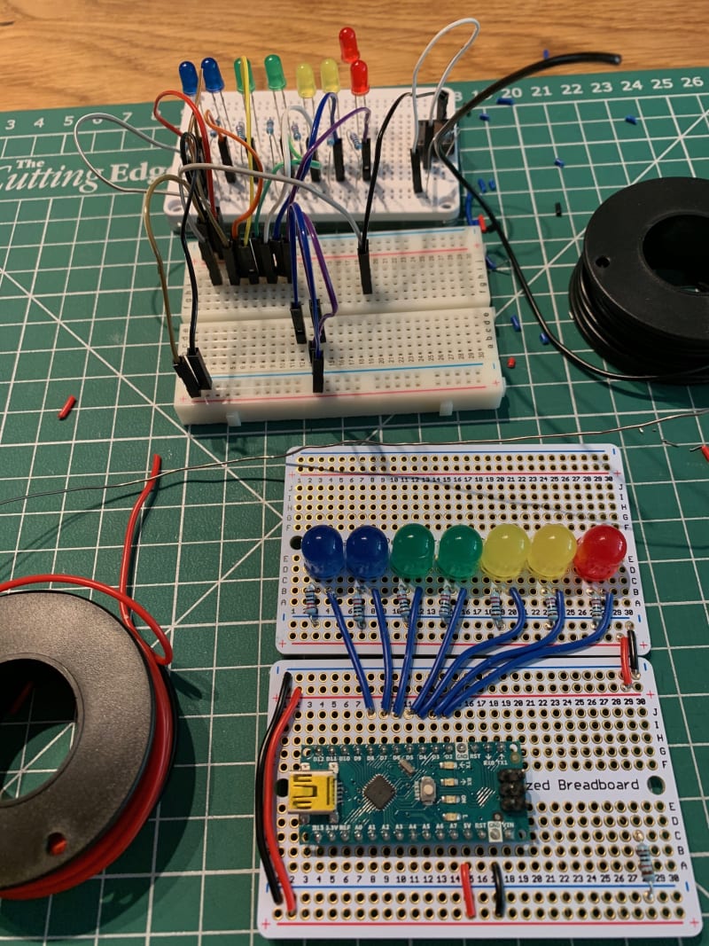
I swapped the hu-uge LEDs for the normal sized one. I moved the huge (10mm) LEDs to the Perma-Proto breadboard. I've started to add resistors and using the non-solder breadboard layout as a reference.
Mick pointed me to this great application (think of it as Scratch for newbies getting into electronics). It helps you layout your electronic bits and pieces.

So this is what it looks likes for my non-solder breadboard blinky badge, instead of looking at the mess of wires.
BTW, if you want to add Adafruit components to layout your project you will need to import these libraries into Fritzing: https://learn.adafruit.com/using-the-adafruit-library-with-fritzing/import-the-library-into-fritzing
Next… Soldering
I’m not the confident in soldering, I’ve been told I’m fine at it. This is the part of electronics that I’m not comfortable. I didn’t attend the final workshop as it was in US Pacific times, so was rather late. So it was a project to do myself at some stage.
I’ve purchased a few Adafruit Perma-proto boards, so with Mick’s support and encouragement, I proceeded with the project. My Perma-proto boards are also half-sized, so I based the layout on the non-soldered breadboard version. The only think I did was moved the button the bottom board, and layout the big LEDs more neatly.
Anyway, here are some pics of my soldering effort with Mick's guidance.

Also notice there's an orange wire bending tool, this is so handy. There's a few to pick from Thingiverse like https://www.thingiverse.com/thing:36108 (which I'm guessing is the one Mick picked and printed as it looks like the simplest and quickest to print).
Here's a video testing the LEDs with voltmeter:
🙌 And here's the final result:

And you can see the previous non-solder breadboard version (top) vs the soldered breadboard version (bottom).
Huge thanks to Chris aka @TechGirlMN for the workshop and Diana Initiative for running the conference.
What's next on this project?
I will need to add functionality to the button, the grab'n'go code doesn't have it, it's modification of one of the example Arduio code.
Also I want to make a case for it, initially a cardboard one, and next one will be 3D printed one when I have an idea of what the case should look like... or I might just stick with the cardboard one. 🤔 😊
One more thing...
I'm thinking of running CircuitPython Day event... and maybe running a live workshop may not be easy, so a pre-recorded video of the workshop and then I can play the video and step through the process, stop it anytime and answer people's questions. What do you think? Interested in getting involved with CircuitPython Day with PyLadies Dublin and Python Ireland? Drop me an email at dublin@pyladies.com.

Top comments (0)