Testing an FPGA's power supply is critical to ensure stable operation, avoid damage, and prevent erratic behavior. Below is a step-by-step guide covering measurement techniques, tools, and common issues.
1. Key Power Supply Requirements
FPGAs typically require:
- Core Voltage (VCCINT) – Low voltage (e.g., 0.9V, 1.0V) for internal logic.
- I/O Voltage (VCCIO) – Higher voltage (e.g., 1.2V, 1.8V, 3.3V) for interfacing.
- Auxiliary Voltage (VCCAUX, VCCBRAM) – For PLLs, block RAM, etc.
Example (Xilinx Artix-7):
Rail Typical Voltage Tolerance
VCCINT 1.0V ±3%
VCCIO 3.3V ±5%
VCCAUX 1.8V ±5%
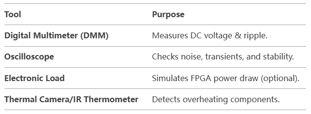
2. Tools Needed
3. Step-by-Step Testing Procedure
A. Visual Inspection
- Check for short circuits, cold solder joints, or damaged capacitors.
- Verify polarity of electrolytic capacitors.
B. Power-On Test (No FPGA Load)
Disconnect FPGA (to avoid damage if power is faulty).
Measure voltages at all power rails using a DMM.
Confirm they match expected values (e.g., 1.0V, 3.3V).
- Check for oscillations with an oscilloscope.
Acceptable ripple: Typically <50mV for core, <100mV for I/O.
C. Power-On Test (With FPGA Load)
Reconnect FPGA and power on.
Monitor voltage stability under load:
Use a scope to check for droops or spikes during FPGA startup.
- Measure current with a DMM (if possible) or a shunt resistor.
D. Dynamic Load Testing
Run a high-load FPGA design (e.g., logic-heavy test).
Monitor:
- Voltage dips during high switching activity.
- Temperature rise in regulators and FPGA.
E. Noise & Ripple Analysis
- Use oscilloscope in AC coupling mode.
- Bandwidth limit: 20MHz (to filter high-frequency noise).
- Probe properly (use short ground springs, not long leads).
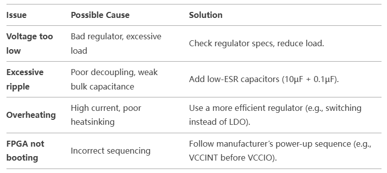
4. Common Power Issues & Fixes
5. Advanced Testing (Optional)
A. Power Sequencing Verification
- Some FPGAs require specific power-up order (e.g., core before I/O).
- Use a scope to track ramp-up timing.
B. Inrush Current Measurement
- Current probe or shunt resistor + scope.
- Ensure inrush doesn’t exceed regulator limits.
C. Long-Term Stability Test
- Run FPGA at full load for hours.
- Log voltage, current, and temperature trends.
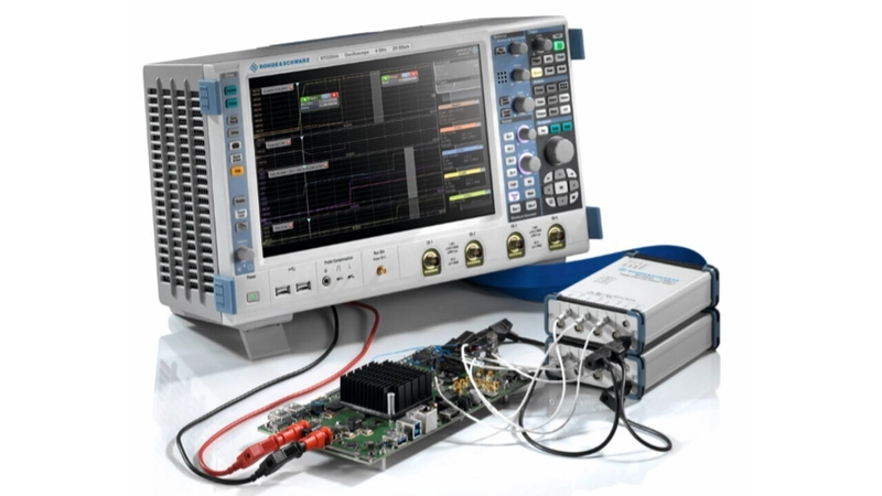
6. Example Test Setup
Using a Bench Power Supply
- Set voltage to expected rail value (e.g., 1.0V for VCCINT).
- Gradually increase current limit while monitoring behavior.
Using a Multimeter & Scope
FPGA Board
├── VCCINT → DMM/O-scope probe
├── VCCIO → DMM/O-scope probe
└── GND → Scope ground
7. Safety Tips
- Double-check polarity before powering.
- Start with low current limits to avoid damage.
- Use isolation if probing high-voltage circuits.
Conclusion
- Test power rails before FPGA connection (no-load check).
- Verify voltage, ripple, and sequencing under load.
- Fix issues early (decoupling, regulator selection).
- Use an oscilloscope for dynamic behavior analysis.

Top comments (0)