Introduction
IoT (Information of Things) devices have become more and more prevalent in everyday life. From home assistants to smart toasters these devices are all over most households and offices. Most of the house appliances utilize WiFi module in order to communicate with the designated API. However, for IoT devices to be able to collect data at a remote location or on the go a SIM module would be needed. In this article we will explore implementing an IoT device to collect and send data on the go.
BOM
Below are the parts that are required for the project. (Note: Though link provided, please purchase at your own risk)
- Raspberry pi (Zero W used for demo, but any model should work)
- SIM7000 (A used for demo, but select based on location) breakout board (breakout boards simplify the circuit for easier development/testing)
- Female-Female jumper wires
- Header pins (for the Zero model this is needed)
- GSM Antenna
- GPS Antenna
Schematic
The wiring is straight forward, breakout board needs 5V so, connect pin 2 (5V) from raspberry pi to the V pin then connect pin 6 (GND) from raspberry pi to G. For UART protocol, connect Receiver pin to Transmitter pin, so R pin connects with pin 8 (Tx), and T pin connects with pin 10 (Rx). Please refer to the below schematic for better guidance.
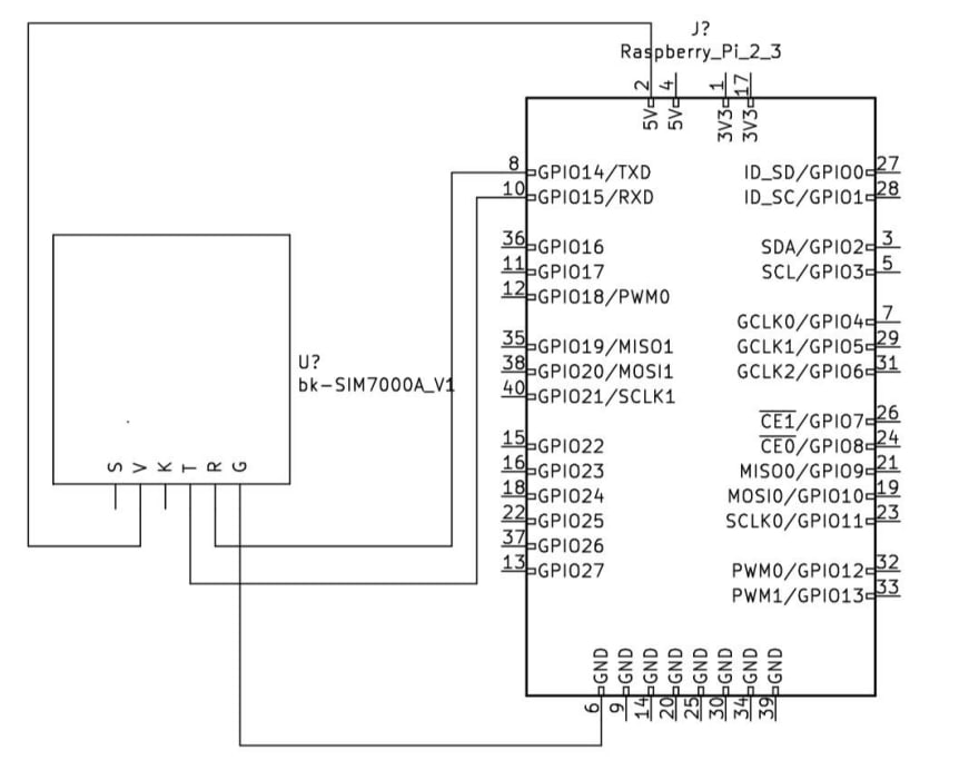
Fig 1.1: Raspberry pi and SIM7000 breakout board schematic
Setting up Raspberry pi
The raspberry pi zero W has a WiFi module that allows setting up the device headless. To do this, please follow this wiki: http://wiki.lofarolabs.com/index.php/Install_Raspbian
Once the device is setup headless or with monitor, keyboard and mouse, please start off with making sure that everything is updated.
sudo apt-get update
sudo apt-get install upgrade -Y
Once everything is updated and the device is ready, please start validating that UART is enabled.
sudo raspi-config- option 5 - interfacing options
- option P6 - serial
-
Would you like a login shell to be accessible over serial?->No -
Would you like the serial port hardware to be enabled?->Yes
With UART configured please check whether or not you see the device we will be interfacing with /dev/ttyS0 with command: ls -l /dev | grep tty.
This project utilizes the UART protocol for communicating with the SIM7000 module. In this case there is a python-serial library that will simplify the communication with the module. However, initially there is a possibility that the device might not respond to commands, this is mostly due to a power issue. This is why standard USB port on laptops/desktops might not be enough to power the device. The recommendation is to first give it 10-15 minutes and see if it responds, if not would recommend trying a different power source. The best result was achieved by using a power brick, but YMMV. During this testing phase it is not practical to run the actual python code as there are already tools for sending UART commands.
Please run the following to install minicom.
sudo apt-get install minicom -Y
Once minicom is installed please run it by specifying the device and baudrate you want to use as well.
minicom -D /dev/ttyS0 -b 115200
Once in, for first time usage please note that to exit press [CTRL]+[A] -> [Z] (Note: not all three together, first two combo, then last key). This is crucial because if the device is not working then screen will be blank and you will not be able to get out, this should save you from that panic attack. For better understanding of what is going on, please press [CTRL]+[A] -> [E] to enable echo and this should allow you to see that the commands are being sent, just no response. For basic tests to see that the device is at least responding, please try the command AT in the minicom window/terminal. This should return OK. Once this is verified we can move onto the next step: Running the Code.
Running the Code
Please clone the library here. To verify this please ensure that the python-serial library is installed, as that is the only prerequisite for this script. Then run using python tracker.py and you should the commands and the output of the commands on the screen. Once done, please schedule it to run on boot by scheduling a cron job. Run crontab -l to check existing cron jobs, then run crontab -e to edit. Please add the following:
@reboot python /full/path/to/tracker.py
to the cron script. (Please comment if something is not working as expected)
Logical Breakdown
The basic concept for the project is to upload data from a low power consuming device on the go using internet to an API then utilize those data points to show the travel history of the device. This was then broken down into three components to simplify the project. The components are API, UI, and the IoT device. The API supports GET and POST request for footprints (data points). The UI displays the footprints on a map, and allows user to get direction to the place where the last ping was received from. Though there are libraries for the SIM modules, the most reliable implementation is through serial library, as the user could follow the official documentation for the AT commands by device model.
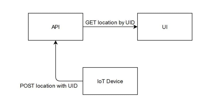
Fig 1.2: Diagram of the project design
Conclusion
The possibilities with IoT devices are limitless, however, because we see them mostly utilizing WiFi for communication which might be discouraged when thinking of outdoor projects. Whether you are concerned about reliability, cost, or simplicity of implementing your ideas the road towards them have already been paved. Hologram provides free data for beginners, SIMcom provides affordable SIM modules with well documented guides, and Heroku provides free easy to host solution for deploying web apps.
All relevant code:
If you would like more information on the code, please let me know and I will create a second part.
If you would like to see a different kind of project please let me know, and I will do my best to implement it.

Oldest comments (0)