Introduction
As a budding cloud engineer, I was recently given the task of creating a three-tier architecture for a web application that previously had a straightforward one-tier architecture. A fault-tolerant, scalable design that could accommodate increasing traffic and demand was the aim. I successfully designed and implemented a three-tier architecture on AWS using multiple availability zones for high availability and fault tolerance after some research and testing. Anyone who wishes to carry out a similar task can use this blog post as a guide.
LongPostAlert!
Architectural Diagram
The first step is to create a three-tier architecture. There are several tools available for this purpose. This AWS webpage provides a summary of several websites that can be used, and I suggest draw.io. A sample architectural plan created is shown below.
Deployment
The resources needed can be divided into various sections which will be discussed below.
VPC
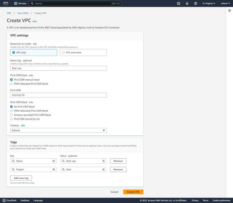
The VPC can be created as shown in the following figure.
Next is to edit VPC settings to enable DNS resolution and hostnames.
Subnets
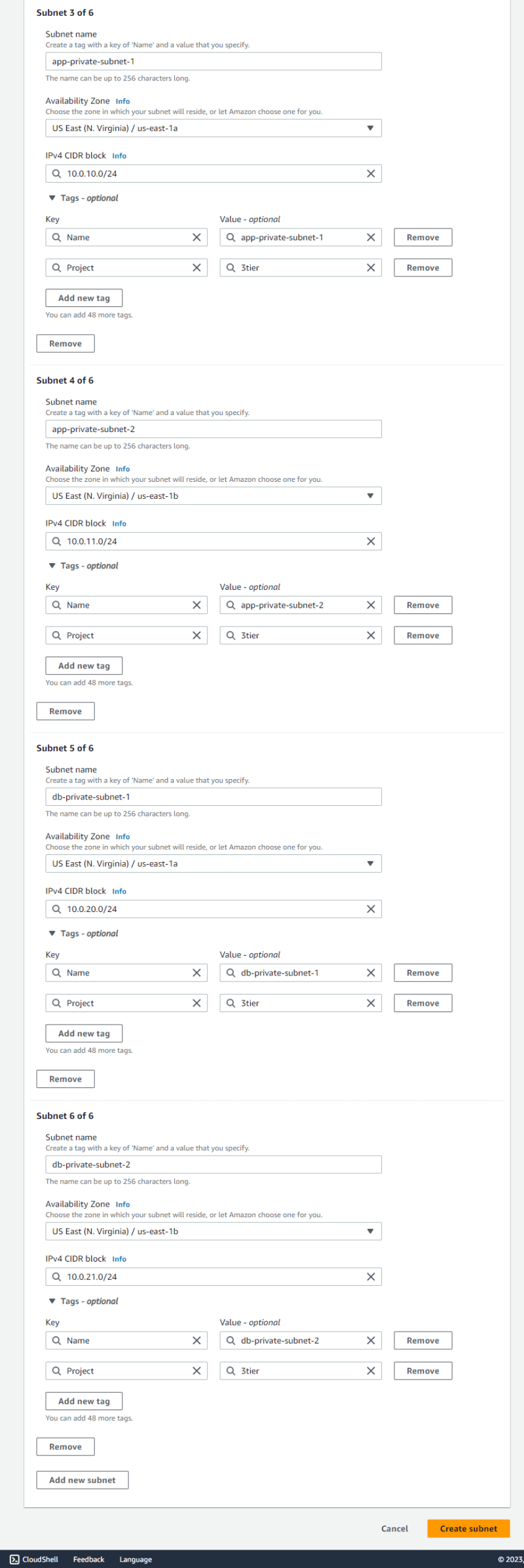
The architecture requires six subnets, with three in each availability zone. Two subnets are private while only one is public in each availability zone.
For the public subnets, their settings can be edited to enable auto-assign public IPv4 settings.
Security Groups
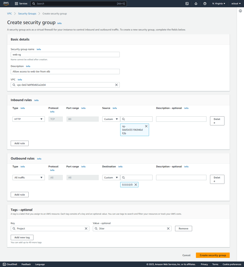
Next is to create the security groups.
- The first is the
web-elb-sgwhich allows HTTP access from all sources.
- The
web-sgis created next which allows HTTP access fromweb-elb-sg.
- The
app-elb-sgis created next which allows HTTP access fromweb-sg.
- The
app-sgis next which allows HTTP access fromapp-elb-sg.
- Finally,
db-sgis created which allows MySQL access fromapp-sg.
Internet Gateway
Since this is a new VPC, an internet gateway has to be created and attached to the VPC as shown below.
Route Tables
When a VPC is created, a default route table is created. Any subnets that have no explicit route table associations will be associated with the default route table.
A web-RT route table can then be created with a route with 0.0.0.0/0 destination with the internet gateway as the target.
The public subnets can then be associated with this route table.
Launch Templates
- Web Tier Launch Template
A launch template is then created to be used in the web tier. This is associated with the
web-sgsecurity group, with auto-assign public IP enabled.
Some user data can be included to enable Apache web server to run in the instances after creation.
- App Tier Launch Template
A launch template is then created to be used in the app tier. This is associated with the
app-sgsecurity group.
Target Groups
- Web Tier Target Group A target group is then created to be used for the web tier.
No instances are registered at the moment, but they will be registered automatically once they will be launched by the Auto Scaling Group.
- App Tier Target Group. This is a similar process to the web tier target group.
Application Load Balancers
- Web Tier
This is set up with the internet-facing scheme. Under mappings, the two public subnets in the two AZs are selected. This is associated with the
web-elb-sgsecurity group.
A HTTP:80 listener is then associated with the WebTierTargetGroup.
- App Tier
This is set up with the internal scheme. Under mappings, the two app private subnets in the two AZs are selected. This is then associated with the
app-elb-sgsecurity group.
A HTTP:80 listener is associated with the AppTierTargetGroup.
Auto Scaling Groups
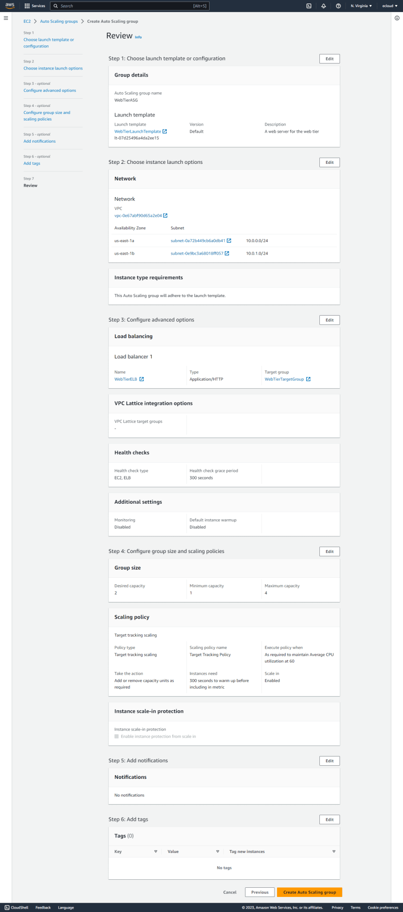
- Web Tier
The
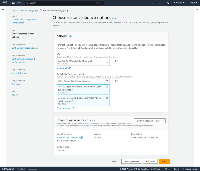
WebTierASGis created and associated with theWebTierLaunchTemplate.
The two web public subnets are selected to be used by the ASG.
This is then associated with the WebTierELB, with ELB health checks enabled.
The group size is selected as shown, with a target tracking scaling policy using the Average CPU utilization metric.
- App Tier
The
AppTierASGis created and associated with theAppTierLaunchTemplate.
The two app private subnets are selected to be used by the ASG.
This is then associated with the AppTierELB.
The group size is selected as shown, with a target tracking scaling policy using the Average CPU utilization metric.
Web Tier Test
After the auto scaling groups are set, it kicks in and creates the instances. Two instances are created initially in each tier since the desired capacity is set to two.
Upon visiting the ELB endpoint, it can be seen that we get responses from both instances as shown below.
However, since the minimum capacity is set to one, once the target tracking policy kicks in and the web servers are idle, the capacity is reduced to one in each tier.
DB Subnet Group
The DB subnet group is created specifying the two availability zones and the two DB subnets created earlier on.
RDS Database Creation
This is created using RDS using the Aurora(MySQL Compatible) engine. Multi-AZ deployment is enabled. The subnet group created in the previous section is selected, specifying the db-sg as the security group to be used.
This creates two DB instances, one in each AZ. One is set as the writer instance in us-east-1b and the other as the reader instance in us-east-1a.
In order to test failover to see what happens if the writer fails, we can see that the writer instance switches to us-east-1a.
CloudFront Distribution
A CloudFront distribution is created with with the web tier ELB as the origin domain using the HTTP protocol. A custom header is added so that requests coming through the distribution will include it. This will be essential to distinguish traffic that come via the distribution and those that go directly to the ELB.
WAF Web ACL
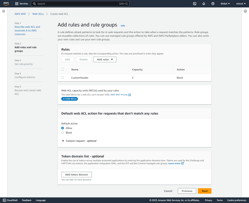
A WAF web ACL is used to block any traffic to the ELB that do not contain the custom header, implying that only traffic that go through CloudFront will be allowed to the ELB.
The CustomHeaderACL is created and associated with the WebTierELB.
A rule is added to block any request that do not contain the custom header specified in the previous step.
The default action is left as Allow to permit any request that does not match the set rule.
CloudFront Test
Traffic that is sent via the CloudFront endpoint is allowed as shown below.
Traffic sent using the ALB endpoint is now denied.
Outro
Think of deleting unused AWS resources like eating your vegetables - it may not be fun, but it's necessary for a healthy and cost-efficient cloud environment 🥦💰💪
Experimenting with these resources can be a fantastic experience, giving you the thrill when you get the desired outcome and even more fun when you have to troubleshoot and figure out why something went wrong.














Top comments (0)