
This tutorial was originally published here
(If this is your first time here, check out my first MicroPython tutorial. Use it to get acquainted with the Wokwi simulator interface so that you are prepared to dive into this tutorial).
Is it just me, or is it getting hot in here? I better go check the thermometer to find out. But have you ever wondered how a digital thermometer actually works? Many of us are taught in school how mercury thermometers tell the temperature, but most of us don't ever learn the magic/physics behind digital temperature sensors. In this tutorial, you will understand how temperature is measured by microcontrollers and you will use the power of MicroPython to do it yourself!
Whether you want to check for a fever, monitor the conditions in a greenhouse or protect your satellite in the freezing cold of outer space, you need to measure the temperature of your system. The most popular sensor for measuring temperature is called a thermistor. A thermistor is a component that has the peculiar property that its resistance changes with temperature. If you put a thermistor into a circuit, you can measure its change in resistance and use that to calculate its temperature. Pretty neat!
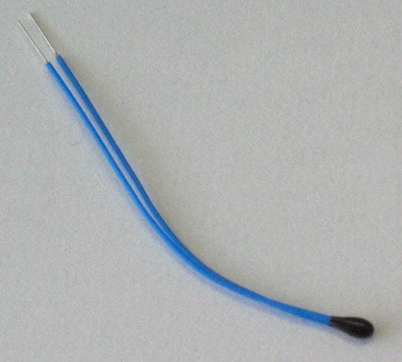 A thermistor (Ansgar Hellwig, CC BY-SA 2.0 DE, via Wikimedia Commons)
Luckily for us, we don't have to buy a physical thermistor to try this out. Our trusty simulator, Wokwi, has a thermistor component available for us to play with. Let's start a new MicroPython project on Wokwi. Click on the 'plus' button at the top of the simulation pane, scroll down and click on 'Analog Temperature Sensor' to add it to the schematic. You will notice that this sensor module has 3 pins: GND, VCC and OUT.
 The temperature sensor module's 3 pins: GND, VCC and OUT
The VCC and GND pins need to be provided with power supply (3.3V output pin) and ground, respectively, from the Raspberry Pi Pico. To understand what the OUT pin is for, let's take a closer look at the components present on this sensor module.
You see the black 'bead' on the left of the module? That's the thermistor. If you look slightly to the left of the 3 pins, there is a small resistor there with a resistance of 10kΩ, i.e. 10000 ohms. The thermistor and the 10k resistor are connected in series, with the OUT pin connected between them. Here is a schematic of the module to show the circuit.
 Schematic of the temperature sensor module
This type of circuit is called a voltage divider, because the voltage you measure at the OUT pin is a fraction of the power supply voltage VCC. In other words, the voltage VCC gets divided between the resistor and the thermistor. The fraction depends on the ratio between the resistance of the thermistor and that of the resistor (i.e. 10kΩ). Using this, and the fact that the thermistor's resistance itself depends on temperature, we can back-calculate the temperature by measuring the voltage on the OUT pin.
Wait a second. Does that sound familiar? If you read the previous tutorial, you'll remember that we measured a fraction of the supply voltage then too! The only difference is that then we were measuring a potentiometer and here we want to measure a thermistor. To measure voltage across the thermistor, we need to use the ADC on the Pico. Let's look at our handy Pico pinout diagram to find an ADC pin.
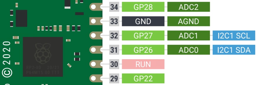 There are 3 ADC pins available on the right side of the Pico: GP26, GP27 and GP28.
We can use either of those 3 pins for our ADC. I am going to choose ADC0, i.e. pin GP26. As in the previous tutorial, we'll connect the sensor's VCC pin to the 3V3 pin at pin 36. And you can connect the GND pin to any ground pin on the Pico; I chose pin number 3. Let's wire it up in the simulator!
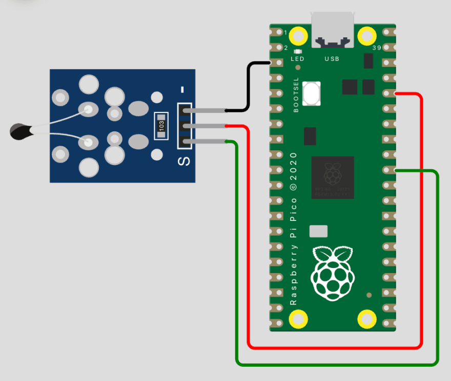 Temperature sensor's pins connected to the Pico
Let's read some data from the temperature sensor to get an intuition for how it changes with temperature. We will write a basic MicroPython script to read the data using the ADC, exactly as in the previous tutorial. Type this into the code editor on Wokwi.
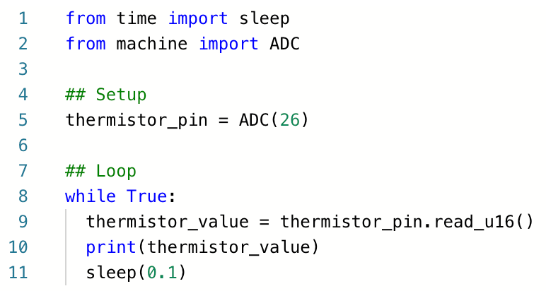 Code for reading and printing data from the ADC
Run the script by pressing the 'play' button at the top of the simulator. By default, the temperature in the simulation environment is constant at a pleasant 24 °C so you will see the same ADC value being output over and over again in the console. To change the temperature, click on the temperature sensor while the simulation is running and you should see a slider. Play around with the temperature and notice the response in the ADC values.
 Sweeping the temperature and observing the ADC output
Interesting! When we decrease the temperature, the ADC value increases, and vice versa. That's because this is an NTC, or negative temperature coefficient thermistor. It's a fancy way of saying that the resistance of the thermistor decreases when its temperature increases.
How exactly does its resistance vary with temperature, though? This is where we would get into some gnarly arithmetic. Since you'd (probably) rather not relive your high-school math class trauma, I won't spend any time deriving the formula between temperature and ADC data. But I do really enjoy showing people stress-inducing math formulas, so I've written it out here for you to see the beautiful horror I shielded you from.
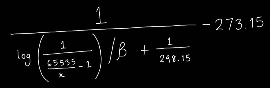 Read it and weep
We do have to put this formula in our code, so let's focus on understanding the two key parameters here:
- The 'x' at the bottom refers to the value we get from the ADC.
- The β (beta) value is different for different thermistors, and it represents a thermistor's exact relationship with temperature.
The astute among you may have also recognized the 65535 in the denominator, which we saw in the previous tutorial. It's equivalent to (2^16 - 1), which is the maximum value that the 16-bit ADC on the Pico will output. The even more astute may recognize the number 273.15, which is the constant factor for converting temperature between Celsius and Kelvin. And the astutest of all will notice that the number 298.15 is just the temperature 25 °C converted to Kelvin. But none of that really matters for writing the MicroPython program, so don't stress 😌
Neat! We now have a way to convert ADC values, i.e. 'x' in the formula above, into a temperature in Celsius. The β value for this particular simulated thermistor is 3950. Let's use this to create a function in MicroPython that converts ADC output to temperature. We will use this function in the main loop to convert the ADC readings and print out the temperature in Celsius. Modify your code to add these two new features, as shown below.
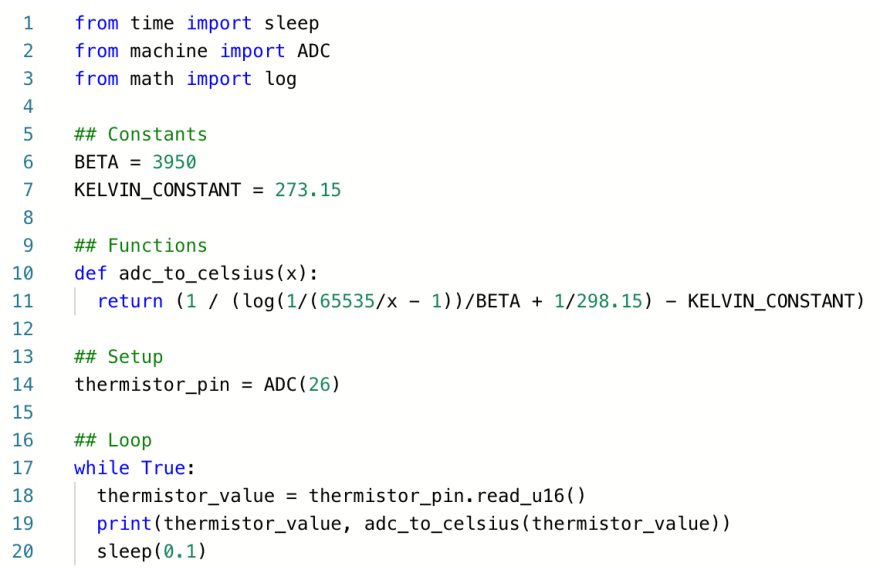 Code for reading thermistor data with the ADC, converting it to Celsius, and printing it out
We have added a new import, the log function from the math library. We then define the constants β and the Kelvin constant. Next, we define the function for the formula I showed you before. It looks a lot nicer when fit into one line of code, doesn't it? No? OK. Just be careful to put all the brackets in the right places. The rest of the code should look very similar, with the main difference being that we're now calling our adc_to_celsius function in the main loop and printing out its value, in addition to the raw value from the ADC.
Let's run the code and see the output we get in the console. We should see the raw ADC value printed on the left side and the converted Celsius value on the right side.
 How to bake a simulated Raspberry Pi Pico
Not bad! Our conversion formula seems to convert the ADC value to temperature quite accurately as there's good correlation between the input temperature and the output. But it's not perfectly precise, is it? You may notice that it's only accurate to 1 decimal place. Let's add a small modification to the code to round the Celsius value to 1 decimal place before printing it out. Luckily for us, there is already a round function built-in in MicroPython's standard library. Let's modify line no. 19 to use this function.
![]() Rounding the output of the adc_to_celsius function to 1 decimal place
Rounding the output of the adc_to_celsius function to 1 decimal place
And that's it! We just built our own digital temperature sensor using a thermistor and the ADC on the Pico. You were very brave for pushing through the math and making it to the end of this tutorial - congratulations!
As always, I have a small add-on challenge for you that will improve your MicroPython skills. Imagine this temperature sensor was being used at a factory where the temperature must be maintained between 15 °C and 35 °C for safety. If the temperature goes outside this safe range, a siren (red LED) should start blinking to alert everyone! Try modifying our project to add this capability. Good luck, and please comment below or reach out to me on twitter if you have any questions or if you'd like to show me your solution 🙂 I'm looking forward to it!
If you found this interesting, do follow/subscribe to be notified of new tutorials. I release tutorials once a week.
This tutorial was originally published here

Top comments (0)