
Hello friends, I hope you are fine. Today, we will discuss the Enhancement Type Mosfet. As we are done with the basic understanding of the regions under which the IV characteristic curve operate, we would now discuss the characteristics of MOSFET specific to their different subtypes. So, let's get started with this type of transistor:
I-V characteristics of N channel enhancement type MOSFET
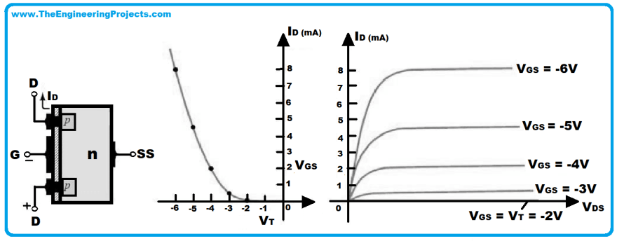
- The characteristics curve for N channel enhancement MOSFET is drawn for the varying values of drain to source current IDS with the voltage VGS which is the gate to source voltage.
- The current would be zero because of the absence of a conduction channel between the source and drain until the VGS which is the gate to source voltage reaches the threshold voltage represented by VT.
- Refer to the following graph for better understanding:

- Under such circumstances what you think the increase in the drain to source voltage would do? Let me make this clear for you, there wouldn't be any increase in the IDS which is the drain to source current, have you thought why? Because the conduction channel is still not there, so there is no point of increasing the current without the conduction channel, you can’t make a banana smoothie without bananas! This phenomenon represents the cut-off region of the graph. We can mathematically write it as: VGS < VT
- In the next step, the Gate to source voltage VGS increases in value increasing the Current IDS, this is represented by the Ohmic region of the V-I characteristic curve. The mathematical expression can be written as: VGS > VT and VDS < VP
- Later on, VGS crosses the threshold voltage VT, keeping the current IDS constant and is represented as the saturated region of the graph. For this region we can write it as: VGS > VT and VDS > VP
- The gate to source voltage VGS keeps on increasing the current IDS even in the saturated region until a defined value of voltage is reached known as Pinch off voltage, you can check this in the saturated region of our graph.
- You can yourself guess the majority of charge carriers involved in the conduction process, can’t you?
I-V characteristics of P channel enhancement type MOSFET
- The transfer characteristics of P channel enhancement type MOSFET are plotted between the varying values of Drain to Source current IDS with the gate to source voltage VGS.
- Refer to the following graph for better understanding:
- The IDS, drain to source voltage remains zero in the cut-off region because the conduction channel is not established until the gate to source voltage crosses the threshold voltage VT. can Mathematically write it as: VGS > -VT
- After crossing the threshold voltage VT the VGS causes an increase in the Drain to source current in the reverse direction, represented by ISD because the conduction channel has been established by now. The region representing this state of affairs is labeled as the Ohmic region on the graph, you can follow the graph step by step for better understanding. For this region we can write the mathematical expression as: VGS < -VT and VDS > -VP
- In the next phase, the VDS which is the drain to source voltage reaches the pinch-off voltage VP, at this stage saturated current flows through the P channel enhancement type MOSFET which is represented by the saturated or active region of the graph. We can summarize the whole scenario by writing it as : VGS < -VT and VDS < -VP
- As the negative value of Voltage VGS increases the drain to source current represented by IDS increases. You can easily point it out from the graph! Scroll up and correlate the values of VGS with IDS, aren't they increasing with the increasing negative value of the voltage?

Top comments (0)