(part one is here and part two is here)
A tutorial using the Oplà Kit to have 2 different IoT devices communicate with each other. This is the third part of the articles about IoT, Heroku and Arduino.
Recently, I received the new Arduino Oplà Kit for testing. To try it out, I decided to create an IoT project with multiple environmental sensors that remotely collect data, then report that data over the cloud and back to my home IoT device. It sounds complicated, but the setup was easy, and it allows for many advanced customizations in the future.
In this article, I'll walk through how simple it is to create a similar setup—the architecture, devices, and code. Where you take it from there is up to you!
The Project
To get started, I created a straightforward project to capture the outside temperature, display it on a device in my home, and compare it to the inside temperature. I also wanted to make sure I created something customizable and powerful, where I could add my own logic to allow for more complicated projects in the future.
Note: For a quick background on IoT terms (Thing, Variable, Sketch, and so on), check out this overview.
Our Architecture
The architecture is simple but very powerful. We will leverage the Arduino IoT Cloud REST and Realtime API to allow two different devices to communicate with each other. In the middle, we'll host a custom Node.js application on Heroku. We'll also use the code my friend Francesco Stasi wrote to help us move the data. The code is entirely open source, with an MIT license, and is available at my GitHub repo. Francesco and I will keep working on the code, if there is interest.
The architecture looks like this:

Our first Thing (Thing 1) is connected via Wi-Fi. It reads data (such as temperature) from the environment and sends the data to the Arduino IoT Cloud. By creating our own Node.js application hosted on Heroku, we are able to get the data from Arduino IoT in near real-time by using the MQTT/WebSockets API.
Once we have the data streaming to our application, we can manipulate the incoming information as needed. For simplicity, we'll simply republish the same values from Thing 1 on Thing 2. (Note: You can only do this if Thing 1 and Thing 2 have identical property names.)
This is all simpler than it sounds. Let’s see how to build it!
What we need:
- 1x Oplà Kit (The kit contains 1x MKR1010 and one year of free service for Arduino IoT.)
- Arduino IoT Cloud account (included in the Oplà Kit)
- Heroku account (the free hobby account should be fine)
- 1x Arduino MKR1010 (a basic Arduino board with Wi-Fi, included in the Oplà Kit)
- 1x MKR ENV Shield (environmental sensors)
Creating Thing 1: the External Sensor
First, open the Arduino IoT cloud dashboard and create an Outdoor sensor Thing with just one variable named "temperature."
As you can see in the image below, the type of the variable is “Temperature sensor (°c).” In the sketch, it is represented as a CloudTemperatureSensor. The property does not need to be set; it is just a sensor, not an actuator, so we do not need any kind of user interaction. To avoid sending too much data to the cloud, I set a threshold of 0.2 C.

Then, I created a new device with my MKR Wi-Fi 1010 and attached it to this Thing.
The whole setup looks like this:

Remember to add the network parameters before uploading your sketch. If you don't, you will get an error message.
Next, I added the MKR ENV Shield on top of the MKR Wi-Fi 1010 and created a simple sketch to send the temperature online. Here is the code of the whole Sensors Sketch.
Besides the print to the serial, there are really only two other important lines: ArduinoCloud.update() to send the data to the Arduino IoT Cloud, and the ENV.readTemperature() method, which allows us to measure the temperature and put it in a variable. Then, that variable will be sent to the cloud.
void loop() {
  ArduinoCloud.update();
  // Your code here
  temperature = ENV.readTemperature();
  delay(200);
}
After uploading your sketch to the board, you should see the following in the serial monitor:
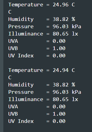
We are registering the temperature every 200ms but only sending it to the cloud if it changes at least 0.2 Celsius. Everything else is recorded and visible locally, though not sent to our cloud application. Feel free to improve the sketch and add your own remote properties.
The In-house Device to Visualize Data
The whole project came to my mind because I just received the new Arduino Oplà Kit for testing. The kit includes many sensors (more or less the same as the MKR ENV Shield), five LEDs, and five capacitive buttons (touch sensors). More importantly, it has a useful battery-powered screen to display data. To power the Oplà Kit, I bought some Samsung 18650 batteries from RS Components.

Because we have such a powerful kit, I decided to create three different visualizations on the screen.
- Button 1 displays the indoor temperature (internalTemperature property) of the Oplà Kit.
- Button 2 displays the outdoor temperature from the MKR Wi-Fi 1010 with the ENV Shield (what I called the Outdoor Board device and the Outdoor Sensors Thing).
- Button 3 shows the difference between the internal and external temperatures.
- LED 1: the LED turns blue if the difference is negative (outside is colder than inside), and red otherwise.
Setting Up the Kit in Arduino IoT Cloud
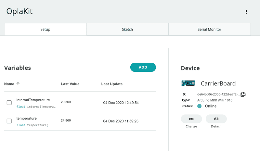
To set up the kit, first be sure to unplug your board; otherwise, it will not work. Then, configure your MKR1010. I named it CarrierBoard as seen in the image here:

After setting up the board, I created a new Thing named OplaKit, then I added two different properties: internalTemperature and temperature. The other board fetches the temperature property, while the internalTemperature comes from the Oplà Kit itself.
The internal Temperature is:
- Type: Temperature
- User interaction: Disabled (read only)
- Send Values: On Change (threshold: 0.1 C)

Note that the temperature property is exactly the same as the property in the Outdoor Sensors Thing.
Creating the Sketch and Adding Interaction
The sketch running in the Oplà Kit seems like magic, but everything is extremely simple. We need to detect when a button is pressed, and change the values accordingly on the screen.
First, we need to add the proper libraries to the sketch to control the LEDs and touch buttons.
// Arduino_MKRIoTCarrier - Version: Latest
#include <Arduino_MKRIoTCarrier.h>
#include <Arduino_MKRIoTCarrier_Qtouch.h>
Then, we need to include the cloud library (automatically done) and tell the system if we are using the case or not. (It will calibrate the sensitivity of the touch buttons.) Then, I set a variable changeDisplayCounter to switch between multiple screens.
#include "thingProperties.h"
MKRIoTCarrier carrier;
bool CARRIER_CASE = true;
int changeDisplayCounter = 0;
The loop is simple. We check each button to see if it's been pressed before displaying data on the screen.
void loop() {
 ArduinoCloud.update();
 // Your code here
 carrier.Buttons.update();
 if (carrier.Button1.onTouchDown()) {
   Serial.println("Touching Button 1");
   changeDisplayCounter = 0;
   printMeasure(internalTemperature, "Int. Temp");
 }
 // Checks if new data are available
 if (carrier.Button2.onTouchDown()) {
   Serial.println("Touching Button 2");
   changeDisplayCounter = 1;
   printMeasure(temperature, "Ext. Temp");
 }
 if (carrier.Button3.onTouchDown()) {
   Serial.println("Touching Button 3");
   changeDisplayCounter = 2;
   printMeasure(temperature - internalTemperature, "Temp. diff");
 }
 internalTemperature = carrier.Env.readTemperature();
 calcDiff(temperature, internalTemperature);
 delay(200);
}
Finally, at the end, we always read the internalTemperature from the kit, and calculate the difference with the external temperature.
The rest of the sketch contains details on the functions:
void onTemperatureChange() {
 // Do something
 calcDiff(temperature, internalTemperature);
}
void calcDiff(float temp1, float temp2){
 if(temp1 >= temp2) {
   //( led index , red , green , blue )
   carrier.leds.setPixelColor(0, 10, 180, 10);
   // return true;
 }
 else {
   carrier.leds.setPixelColor(0, 10, 10, 180);
   // return false;
 }
 carrier.leds.show();
}
void printMeasure(float temp, String name){
 int colors[] = {ST77XX_RED, ST77XX_BLUE, ST77XX_YELLOW};
 int index = 0;
 Serial.println(name);
 Serial.print(temp);
 Serial.println(" C");
 // Reset screen
 carrier.display.fillScreen(ST77XX_BLACK);
 index = changeDisplayCounter % 3;
 carrier.display.setTextColor(colors[index]);
 carrier.display.setCursor(30, 100);
 carrier.display.setTextSize(2);
 carrier.display.println(name);
 carrier.display.setTextSize(4);
 carrier.display.setCursor(50, 120);
 carrier.display.print(temp);
 carrier.display.setTextSize(2);
 carrier.display.print(" C");
}
Here you can find a full copy of my Oplà Kit Sketch.
As of now, the second sketch will not receive any kind of value for the variable temperature because that data lives in the MKR Wi-Fi 1010. Though it is sent to Arduino IoT Cloud, it is not yet sent back to our Oplà Kit. We can solve this by creating our own Node.js application to relay the data.
Creating a Custom Node.js Application on Heroku
To create our custom application, we can use two different kinds of Arduino IoT APIs: one is the REST API, and the other is a real-time MQTT/WebSocket API. The latter is not documented yet, but luckily a JavaScript client is available. You can find the two JavaScript modules here: one is the Arduino IoT Js Client, and the other is the Arduino IoT Js lib.
To interact with the APIs, we will need an API token. You can find yours by clicking the Integrations button at the top of the screen:

Be sure to keep your API key handy. We will use it in a moment.
My friend, Francesco Stasi, is an amazing developer. (You can find him on GitHub.) He helped create the application that proxies a property of a first Thing to another property with the same name in a second Thing.
The whole software is really small, and you can find it in my own Js-IoT-Proxy GitHub repository. The software is designed to be developed locally and deployed to Heroku. The main part of it is visible in this snippet of code available on the repo.
// Register a callback for every property in the object to keep the values
updatedObject.keys(thingProperties).forEach((propertyName) => {
   console.log(`${thingId} - register callback for ${propertyName}`);
   ArduinoIoTCloud.onPropertyValue(thingId, propertyName, (newValue) => {
     console.log(`${thingId} - property ${propertyName} changed`);
     thingProperties[propertyName].value = newValue;
     // Invoke the proxy callback
     proxyThingProperty(thingId, propertyName, newValue);
   });
 });
 return {
   // Get the array of known properties names
   getPropertiesList() {
     return Object.keys(thingProperties);
   },
   // Get the value of a property
   getPropertyValue(propertyName) {
     return typeof thingProperties[propertyName] !== "undefined"
       ? thingProperties[propertyName].value
       : null;
   },
   // Set the value for a property
   setPropertyValue(propertyName, newValue) {
     console.log(`${thingId} - writing ${propertyName}, value: ${newValue}`);
     return ArduinoIoTCloud.sendProperty(thingId, propertyName, newValue);
   },
 };
As you can see, if the two properties have the same name, the devices communicate with each other. The logic is visible in the proxy.mjs file.
Deploying the Application
I have been a Linux Engineer for quite a long time. However, when I need something robust that works out of the box without any maintenance, I prefer to use Heroku.
To deploy the application, I used a very handy feature I recently discovered: the GitHub automatic deploy feature. Every time I merge to main, the app immediately shows up in my Heroku panel.

We are only missing a few things to make all this work. We need to create and store different environment variables containing the following:
- The Arduino API app ID (IOT_CLIENT_ID)
- The Arduino API Secret Key (IOT_CLIENT_SECRET)
- The Thing ID of the OutDoor Sensors (THING_ID_FROM)
- The Thing ID of the OplaKit (THING_ID_TO)
We can do all of this by using the Heroku settings panel in our dashboard.

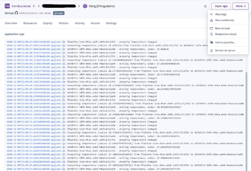
Finally, we can deploy the app and check the logs. Now, every time the temperature changes in the ENV Shield, you can see it being sent to the Oplà Kit in real-time.
Here is how everything looks like on the device itself. You can see the internal temperature by clicking Button 1.

With Button 2, we get the external temperature.

And, finally, with Button 3, we see the temperature difference. The LED will turn blue if the external temperature is less than the internal. Otherwise, it will be red.

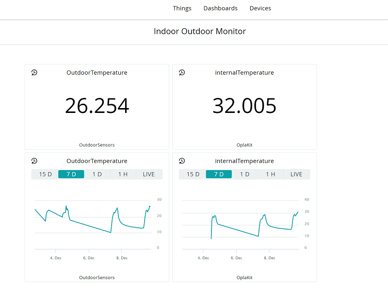
To record the temperature, I created a dashboard in Arduino IoT Cloud by directly adding the Things to our dashboard.
If you want your system to be even more advanced and interactive, you can also install the Arduino IoT Remote app.
Resources
To simplify the system-creation process for you, I collected all the information you need.
Ideas for the Future
That's it! Now you have a fully functional IoT sensor that records outside environment variables, relays them over the cloud, and reports them to a second device in your home. In the future, I plan on further enhancing this by creating my own mobile or web application with a custom interface. (It should be simple with the JavaScript client we used already.) And then, on top of that, I'd like to store all the data points in my own Heroku Postgres instance, and share them via Heroku's Dataclips.

Top comments (0)