Building a joystick interface for the RC2014 Z80 computer. Maybe I’ll learn some more Z80 while also trying to write a simple game.
Watch the video!
How old joysticks work
Back in the old days, joysticks (not “game controllers”) looked like this, with a stick and one action button. The stick moved in 8 directions and the button was used to perform whatever in-game action was required. Usually shooting aliens.
One button, no more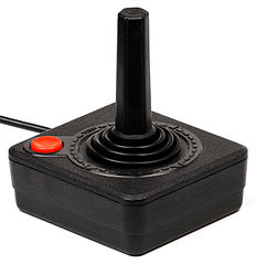
The joystick was a very simple device, having nothing more than five switches inside it; the good ones used microswitches, the less-good ones used mushy leaf springs or pieces of metal that pressed together. On the end of the cable was a 9 pin d-sub connector wired like this
9 Pins is enough for anyone
Moving the stick closed the corresponding switch which connected the ground pin and relevant direction pin. The computer used this to sense which direction was being pressed.
How the RC2014 Joystick Interface Works
I have the version 2.0 joystick board, which doesn’t match the schematics on the RC2014 website, and is slightly different to the Atari joystick standard. The directions and buttons match up, but instead of a ground connection on pin 7, pin 8 has +5v. The joystick I own doesn’t even have a connector in the plug at pin 8, so I had to bridge pins 7 & 8 together. The logic is reversed - pressing a button on the joystick connects +5v through the joystick and down whichever pin was selected. This then goes through a bus transceiver chip and directly onto the Z80 data bus.
Using it with Z80 assembly
The joystick interface is really easy to use. It is configured to be IO ports 1 and 2, and reading from either port returns a number. The number corresponds to each direction and button and is placed in the ‘a’ register.
| Direction | Value |
|---|---|
| Up | 1 |
| Down | 2 |
| Left | 4 |
| Right | 8 |
| Fire | 16 |
Multiple button presses are added together - pressing fire and up returns 17, and so on.
The following SJAsmPlus assembly code will display the appropriate buttons.
    OUTPUT joytest.z80

    ORG $8000

    ld de,starttxt
    call print
loop:
    in a,($1) ; read port 1
    ld (button),a ; copy the byte read
fire:
    and $10
    cp $10
    jp nz,up
    ld de,firetxt
    call print ; then fall through to up
up:
    ld a,(button) ; put byte read back
    and $1 ; should have 1 in a
    cp $1 ; do we have 1 in a?
    jp nz,down ; no, go to next one
    ld de,uptxt ; print up
    call print ;
down:
    ld a,(button)
    and $2
    cp $2
    jp nz,left
    ld de,downtxt
    call print
left:
    ld a,(button)
    and $4
    cp $4
    jp nz,right
    ld de,lefttxt
    call print
right:
    ld a,(button)
    and $8
    cp $8
    jp nz,end
    ld de,righttxt
    call print
end:
    ld a,(button)
    and $17
    cp $17
    jp nz,loop
    ret

print:
    ld c,$06
    rst $30
    ret

; data
button:
    db 0
uptxt:
    dz "UP\r\n"
downtxt:
    dz "DOWN\r\n"
lefttxt:
    dz "LEFT\r\n"
righttxt:
    dz "RIGHT\r\n"
firetxt:
    dz "FIRE\r\n"
starttxt:
    dz "Joystick Test - UP + FIRE to quit.\r\n"
Z80 Development tools
- SJAsmPlus
- z88dk
- SBC Monitor
The following Bash script runs SJAsmPlus to compile the Z80 assembly into a binary file. This is then converted into an Intel HEX format dump. To load this into the RC2014 I use its monitor and just paste the HEX dump directly into it. The monitor is able to place the code directly into RAM ready to be run.
I’m not actually using Z88dk for anything but its ‘appmake’ tool which generates the HEX dump.
#!/bin/sh
appmake +hex --org 0x8000 -b printchar.z80 -o printchar.hex
# Tools
ASM=./sjasmplus
HEX=appmake
HEXARGS="+hex --org 0x8000 -b $1.z80 -o $1.hex"

# Compile the z80 file
$ASM $1.asm && $HEX $HEXARGS

Top comments (0)