OSI Model
The Open Systems Interconnection (OSI) model is a reference model which provides a standard for different computer systems to be able to communicate with each other using protocols. It splits data communication into seven abstract layers. The modern internet is based on the TCP/IP model which strips away many abstractions from the OSI model. But still, the OSI model is widely used as it helps to analyze and troubleshoot networking problems by breaking any problem into one specific layer.

1. Physical Layer
- Devices - Ethernet cables, Optic fiber cables, Network interface cards, etc.
- Protocol data unit - Bits.
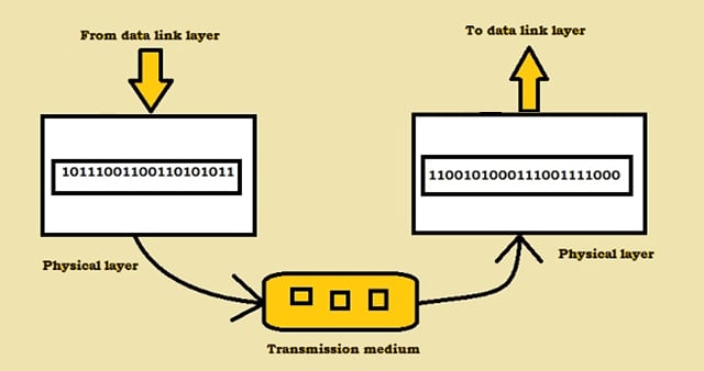
The physical layer is responsible for carrying bit streams over a physical medium. It defines the encoding of bit streams (0’s and 1’s) to electrical or optical signals in order to transfer data through a transmission medium. It defines the transmission rate - numbers of bits sent per second. For example, wifi drivers in our devices use radio waves to transmit bits in the form of wave frequencies to routers which are then encoded back to binary code to transmit over the physical medium.
2. Data Link Layer
- Devices - Switches, Network interface cards,Access Point, etc.
- PDU - Frames.
- Addressing scheme - MAC address.
The data link layer is responsible for moving frames from one node to another. At the sender’s end, it divides the stream of bits coming from network layer into blocks to form frames and later the frames are encoded into 0’s and 1’s and are transferred to the physical layer. Each frame contains a frame flag and a header. It encapsulates source and destination MAC address in the header. At the receiver’s end, the data link layer assembles all the bits from the physical layer back to frames. The data link layer has 2 sub-layers Logical Link Controller(LLC) that communicates with upper layer networking software and the other one is Media Access Controller(MAC) which encapsulates sender’s and receiver’s physical addresses.
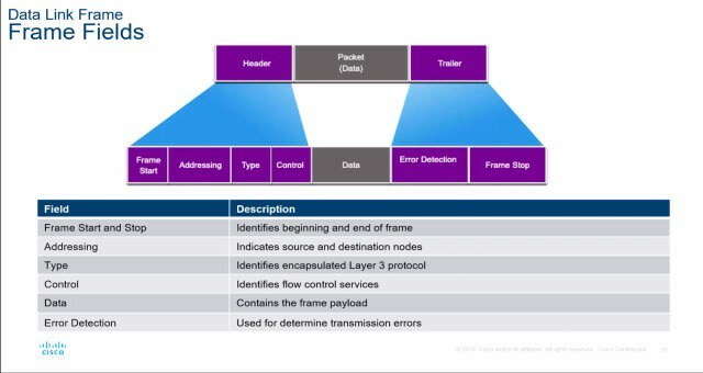
Data Link Layer is also responsible for flow control to impose a control mechanism to restrict the number of frames or data the sender can send before the data overwhelms the receiver and ensures reliability to the physical layer by adding a mechanism to detect lost or damaged frames. Each network interface card embedded in a networking device has a unique MAC address to uniquely identify the device. A Switch is a layer 2 device, it only understands MAC addresses and it maintains CAM (Context address memory) table in its memory to store a mapping of MAC addresses to its assigned port.

3. Network Layer
- Devices - Routers, multilayer switch etc.
- PDU - Packets.
- Addressing scheme - IP address.
The network layer is responsible for end to end delivery of a packet from source to destination. The network layer encapsulates a header with the TCP header coming from the above transport layer. The header includes IP address of the source and destination machines and other information. MAC addresses are useful for internal communication to forward frame from one NIC to another whereas IP addresses are used for external communication to transmit packets from one end to the other end.
 A Router de-encapsulates the received frame and encapsulates next hop’s MAC address in a new frame after reviewing packet's Layer 3 information in its routing table.
Each device connected to the internet is assigned a unique IP address by the internet service provider. An IPV4 address can be in the form of : 203.0.113.112. An IP address has 2 parts the first is network ID to identify which network the address belongs to and the second is host ID to identify which device the packet belongs to in the subnet.
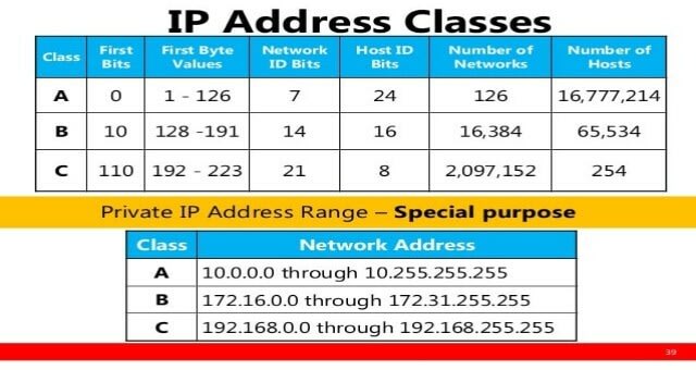
Class A network can connect millions of devices which means
there could be congestion in the network which becomes difficult for a packet to reach to its destination. This is where a subnet is used where a network divided into two or more networks that efficiently routes a packet to its destination. Router is a Layer 3 device. It maintains routing tables in its database to identify the network ID from the packet’s IP address using subnet mask and forwards it to the assigned interface to reach its destination.
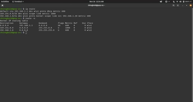
Each entry in the routing table consists of the following entries:
- Network ID: The network ID or destination corresponding to the route.
- Subnet Mask: The mask that is used to match a destination IP address to the network ID.
- Next Hop: The IP address to which the packet is forwarded.
- Outgoing Interface: Outgoing interface the packet should go out to reach the destination network.
- Metric: A common use of the metric is to indicate the minimum number of hops (routers crossed) to the network ID.
4. Transport Layer
- Devices - Load balancer, firewall, etc.
- PDU - Segments.
- Addressing scheme - Port.
The Transport layer is responsible for process to process delivery. Transport layer determines how to deliver data across the network and helps to distinguish data streams.The transport layer encapsulates the header on the payload coming from the application layer. The header contains information like sender and receiver’s port address that helps to identify each application process and contains protocols for communication. A process is a program in execution. Computers run multiple programs at the same time and operate on multiple processes like downloading your favorite movies, playing favorite E-sport game, streaming to spotify and watching Youtube videos on multiple tabs, all these applications create processes and it's the Transport layer’s responsibility to ensure that each of the arriving packet delivers to the right application process.
 For every new application I open on Brave, a new process is created and a random port is assigned to the process by the kernel.
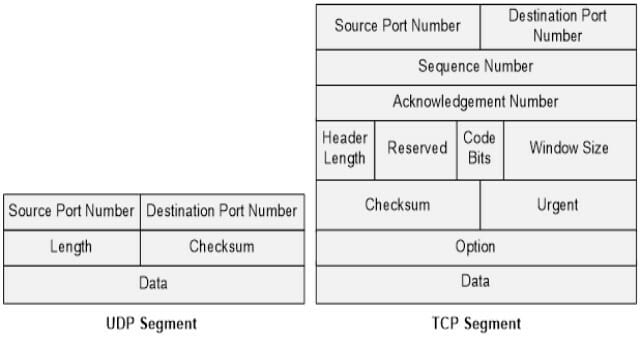
There are popular interprocess communication mechanisms like pipes, sockets and shared memory. Sockets paves the virtual path for inter-process communication between 2 processes in the client server architecture. It creates an endpoint for communication between two process Each socket address is combined with an IP address and a port number. Sockets are of many types but most commonly used are Stream sockets and Datagram sockets. Stream sockets are implemented by Transmission Control Protocol (TCP), they are created when the application program requires reliability, connection oriented and full duplex communication. A TCP connection is established via three way handshake before sending or receiving packets. Datagram sockets are implemented by User Datagram Protocol (UDP), they are created when application requires unreliable, connectionless and fast delivery communication with minimum overhead.
5. Session Layer
The session layer is responsible for establishing, closing and managing sessions between 2 endpoints. The session layer receives encoded encrypted data from the previous layer(presentation layer) and adds session id so the server can identify each client requests because HTTP is a stateless protocol and a TCP connection is terminated after every response. It performs authentication and authorization to secure connections.
6. Presentation Layer
The presentation layer deals with syntax and semantics of the data shared between two systems. At sender’s side the application layer sends data to presentation layer that performs encoding, encryption and compression. Data encryption is a process of converting a plain text to cipher text. At receiver’s side the data from the transport layer is decoded, decrypted and decompressed. For example objects should be formatted in order toget stored or transmitted across network, so applications developers often stringify objects to JSON, this process of encoding data into series of bytes is called serialization. Although in the TCP/IP reference model the application layer implements services of both presentation and session layer.
7. Application Layer
The application layer is responsible for providing services to applications to access the network. Any Web application itself is not the part of the application layer but the services that are provided to the end-users using protocols are part of the layer.
The application layer provides the following main functionalities with the help of application layer protocols:
- Web surfing - Hypertext Transfer Protocol
- Email - Simple Mail Transfer Protocol
- File transfer - File Transfer Protocol
- Network virtual terminal - Telnet
The HTTP protocol is used to exchange data on the Web. It is the language of the Web. HTTP is not only used to fetch hypertext documents but also PDFs, images, etc. It is a stateless protocol however we store client information in cookies and send it in every request to keep the system stateful and to keep the session alive so the server remembers the client. HTTP relies on TCP services to not lose messages and provide a reliable connection.
 HTTP GET request is sent only after the application establishes a TCP connection through 3-way handshake successfully.
REFERENCES
https://www.cloudflare.com/learning/network-layer/what-is-a-subnet/
https://www.man7.org/linux/man-pages/man2/socket.2.html
https://www.geeksforgeeks.org/socket-in-computer-network/
https://www.youtube.com/watch?v=iC86ZhJ6v2Q
https://www.youtube.com/watch?v=eNF9z5JNl-A&t=902s
https://afteracademy.com/blog/what-is-the-osi-model-and-how-it-works
https://afteracademy.com/blog/what-is-the-osi-model-and-how-it-works
https://developer.mozilla.org/en-US/docs/Web/HTTP/Overview
https://www.youtube.com/watch?v=oVVlMqsLdro

Latest comments (0)