
Introduction
LEDs are probably the best thing that ever happened in electronics, they go well with absolutely everything (like raisins, pretty much) and as it turns out, they’re pretty simple to work with.


This tutorial will demonstrate the basics of working with a simple microcontroller board (an Arduino micro) and using it to control an LED. This is the final part of the Crash Course on Electronics series, and once finished with this practice, you should be familiar with working with a breadboard and basic components to start building your own little electronics projects. Hooray!
Required Material

- Breadboard.
- Arduino board. For this tutorial, I'll be using an Arduino Micro, because that's what I have here, but you can use a different Arduino board.
- 1 regular LED.
- 1 220ohm resistor.
- 2 Jumper Wires.
If you haven't yet, check out part 2 of this guide: Putting Together a Budget Inventor's Kit
Here's a closer look at the items we're gonna use:

Arduino board
The Arduino Micro is a compact microcontroller board based on the ATmega32U4 microcontroller.
Breadboard

The breadboard has a series of trails with perforations where you can connect components. Each numbered row usually has 5 holes that are interconnected, so placing a wire and a component in the same row, for instance, is the same as if you were connecting them directly. The two lines of perforations at each side of the board are typically used to connect power (red line) and GND (blue line).
Regular LED
LED comes from "light-emitting diode". Regular LEDs have two legs, one positive (anode) which is usually the longer one, and a negative (cathode) which is usually the shorter leg. You will normally connect the positive leg of an LED to a resistor (around 220 ohm or higher up to 1k) and the negative leg to GND.
Resistor
Resistors are a fundamental electronic component. They are used to limit current flowing through a circuit. Resistors can have many different pre-defined values, measured in ohms. The bigger the value, the bigger the resistance, which means less electrons passing through.
Jumper Wires
Jumper wires are simple reusable wires that can be easily connected to the breadboard and components for prototyping.
Getting your Environment Ready
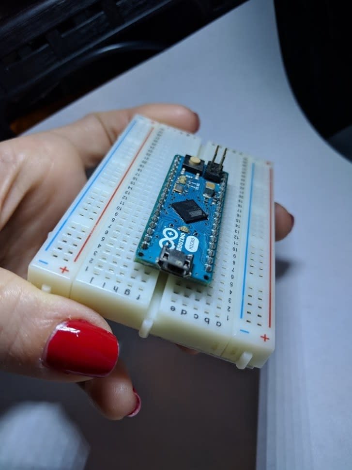
Let's start by getting the environment ready. If you are using an Arduino Micro, "plug" it to the breadboard, making sure to position each side of pins in a different side of the breadboard, so they don’t short-circuit. It should look similar to this:
You can now connect the USB cable to the board in order to turn it on.
Go to the Arduino website and download the Arduino IDE. Once you get it installed, select the right board in the menu Tools -> Board. For the Arduino Micro, you should select Arduino / Genuino Micro. You might need to also select the port for communication, under the menu Tools -> Board -> Port. The port selection works only when the board is connected.
When you turn the board ON by plugging the USB cable, you should be able to get information about it by going to the menu Tools -> Get Board Info.
Consulting the Board Pinout
It’s always interesting to have at hand the board pinout. It will show you details about the board, the available pins and other information. You can find pinouts for all the most popular boards easily with a Google search – you can even go to “images” directly to get what you need quickly.
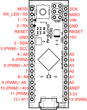
This is how a simple pinout looks like for the Arduino micro:
Getting Started
Now that you’re all set up, it’s time to upload your first sketch to the board. Open the basic blink example on the IDE through File -> Examples -> 01. Basic -> Blink. Have a look at the code to get a basic idea of how it works:
// the setup function runs once when you press reset or power the board
void setup() {
  // initialize digital pin LED_BUILTIN as an output.
  pinMode(LED_BUILTIN, OUTPUT);
}

// the loop function runs over and over again forever
void loop() {
  digitalWrite(LED_BUILTIN, HIGH);   // turn the LED on (HIGH is the voltage level)
  delay(1000);                       // wait for a second
  digitalWrite(LED_BUILTIN, LOW);    // turn the LED off by making the voltage LOW
  delay(1000);                       // wait for a second
}
You’ll notice that the program has two functions, a “setup” and a “loop”. They are quite self-explanatory. This example uses the built-in LED from the Arduino board, which is defined by the constant “LED_BUILTIN”. As you’re gonna see in the next example, we can change this to a different pin in case we are using an external LED.
When you feel ready, hit the “upload” button (right arrow) to send the code to the board. In a few seconds, you should see the built-in LED in the board starting to blink.
Using the External LED
That was interesting, but very simplistic. For the next example, we are going to use our external LED, and for that, we'll need to build a little circuit. Exciting!
Creating your First Circuit
Circuits are, basically, paths in which electricity can run.
You can think of a circuit as a program. It has a very specific flow of execution (electricity) that can be altered by controls: function or method calls, conditionals and such. In a circuit, such controls are implemented in “bare metal” through the use of components such as buttons, resistors, capacitors, LEDs, you name it.
Our circuit is very basic. We are going to connect an LED to the pin 6 of the Arduino Micro board. To connect the LED, we’ll need a 220ohm resistor (values up to 1k can still light up the led).
Without further ado, let’s check the diagram representing the circuit we want to build:
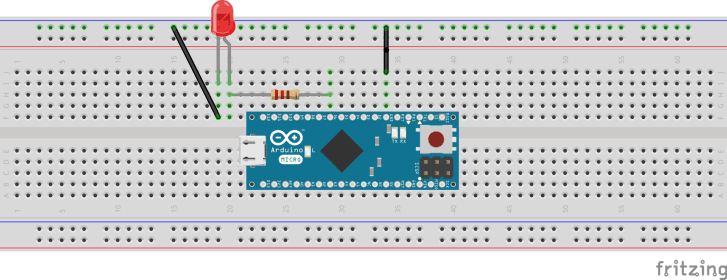
As you can see from the diagram, the positive leg of the LED (anode, right leg in this diagram) is connected to the resistor, which is then connected to the pin number 6 on the Arduino board.
You might be wondering what the black wires are doing there. They are connecting the negative leg of the LED (cathode, left leg in this diagram) to one of the GND pins on the Arduino board.
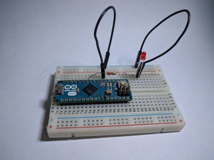
Here’s how my circuit looks like IRL:
Now, we are going to make a slight change to the previous “Blink” example, so it uses pin 6 instead of the built-in led pin it was using before. To make the code more versatile, we’ll create a variable with the pin value so it’s easier to change it, in case we need to.
Here’s the updated code:
int led = 6; // we are using pin 6 for the led
// the setup function runs once when you press reset or power the board
void setup() {
  // initialize digital pin led as an output.
  pinMode(led, OUTPUT);
}
// the loop function runs over and over again forever
void loop() {
  digitalWrite(led, HIGH);   // turn the LED on (HIGH is the voltage level)
  delay(1000);               // wait for a second
  digitalWrite(led, LOW);    // turn the LED off by making the voltage LOW
  delay(1000);               // wait for a second
}
Additional Example: using PWM
PWM stands for “Pulse Width Modulation”, which is basically a type of digital signal that emulates an analog signal. While a digital signal can only be HIGH (5v) or LOW (0v), PWM implements a way for translating digital signals into analog waves (of sorts) so we can use a graduating range of values through a pin – for this example, we are going to use PWM to make our LED fade in and out, instead of simply blink.
Now, if you have a look at the Arduino micro pinout image, you’ll notice that some of the pins have the word “PWM” close to the pin number. This means that pin supports a PWM output, and that’s what we need in order to make our LED fade.
As you’ll notice, the pin we chose for the previous example (pin 6) has PWM support, so we actually won’t need to change anything in our circuit. Only the code needs to be changed.
Let’s open the Fade example. On the Arduino IDE, go to the menu File -> Examples -> 01. Basic -> Fade. Now change the pin number from 9 to 6 and you should be ready to upload the new example.
Here’s the code (including the pin change and stripped from comments):
int led = 6; // our led uses pin 6
int brightness = 0;
int fadeAmount = 5;

void setup() {
 pinMode(led, OUTPUT);
}

void loop() {
 analogWrite(led, brightness);

 brightness = brightness + fadeAmount;

 if (brightness <= 0 || brightness >= 255) {
   fadeAmount = -fadeAmount;
 }

 delay(30);
}
Conclusion
In this final part of the Crash Course on Electronics Series, we saw how to set up an Arduino environment and how to create a simple LED circuit for the blink example included in the Arduino IDE. We also saw how to use PWM for a fade effect.
From here, you can start tinkering with other basic components such as buttons and RGB LEDs (which are basically 3 tiny LEDs encapsulated into one, sharing a common anode or cathode leg).
If you have suggestions of other tutorials you would like to see here, feel free to leave a comment!
See you next time \,,/

Latest comments (2)
Amazing. keep going.
Now I really want to make some things.
Really useful tutorial Erika, bookmarked (whole series). 👍
Thanks,