Staging a critical machine incident that causes an emergency shutdown of the model
To detect and immediately react to incidents is a classic use case for Industrial Internet of Things (IIoT) applications. Of course, you don’t want to mess with production machinery in a factory to develop your software application. Using a model and simulator to stage, record, and replay incidents provides flexibility to prototype, iterate, and test your software without touching actual factory machines.
Simulating incidents requires a baseline data stream that represents normal operations of a machine. For example, a constant flow of product data. A singular event then interrupts such a constant stream. This might be something like sensor data of an incident.
For the abstract IIoT factory model, we want to stage several scenarios with various product data and incident data. We want to flexibly develop software or data pipelines that react to sensor data that indicates incidents. And we want to see the results of such reactions to sensor data in the real world equipment of our model.
In our previous blog post, we explained how to create a camera-based product-reader model reading QR code strips. We also showed how to flexibly create such QR codes from a JSON file with product data.
In this blog post, we share how to create a physical conveyor-belt model and stage an incident that causes an emergency shutdown of the model.
Staging an incident with the product reader
To prepare incident data, use the same method as for producing the QR code based product data stream you find in our previous post. Instead of strips with multiple product variants, we produce a strip with incident data compatible with our open source IIoT Server. Our file in ./qr_data/ is called “incidents.json” and looks like this:
[
  [
    {"name":"incident","value":"FOREIGN_OBJECT"}
  ],
  [
    {"name":"incident","value":"PERSON_TOO_CLOSE"}
  ],
  [
    {"name":"incident","value":"FIRE_ON_BELT"}
  ]
]
Next, run the script ruby ./make_qr_strip.rb incidents, open the generated HTML page “./qr_strips/incidents.html” in a web browser, and print it. Cut out the QR codes and glue them to the back of a coaster. We recommend writing the type of incident on each coaster to recognize them later.
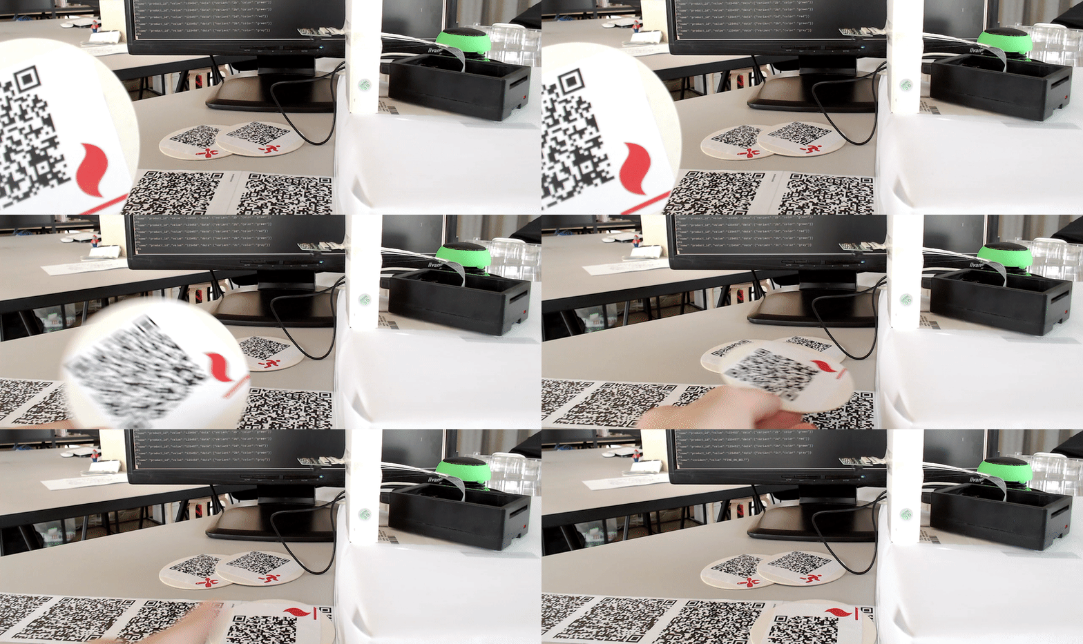
Put the incident-data coasters on your product data strip and watch the product-reader model read the incident data and print it to your screen.
How to 3D-print the IIoT factory model’s conveyor belt rollers
We want to send the warmest thank you to the etventure tech guild team for their great support on building the model’s hardware and sensors! This wouldn’t be possible without your help.
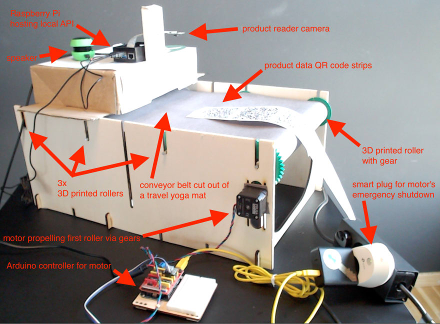
Our factory model has a total of four 3D-printed rollers, each of which consists of two halves that screw together. One of these rollers propels the conveyor belt and has a special design. Instead of an even surface, this roller has a lot of grip and a gear attached, so the motor can propel it.
Building the IIoT factory model is a work in progress, and we welcome you ideas for optimizations on our Discord channel. Find the current versions of our 3D models for download here.
How to laser cut the IIoT factory model frame
Thanks to our friends at the etventure tech guild team, we are using a wooden laser cut frame for the model. If you have carpentry skills, you could build a similar frame, of course.
Our IIoT-factory model frame has two side panels with a couple of notches for the 3D printed rollers, the stabilizing bridges and the motor. The stabilizing bridges between the side panels are in a separate model file. Their current versions are all available for download here.
How to attach a stepper motor to the IIoT factory model frame
Select a corner of your frame to place your stepper motor and mount it. Do not tighten the screws too much, since adjustments may be necessary after mounting the rollers. On the inner side of the panel, attach the small 3D printed cogwheel to the stepper motor.
Pick the 3D printed roller with the attached gear, turn it so that the gear is in the corner of the motor and put it in the notch. Adjust the position of the motor so that the roller rests easy, but the motor’s small cogwheel still tightly fits into the roller’s gear.
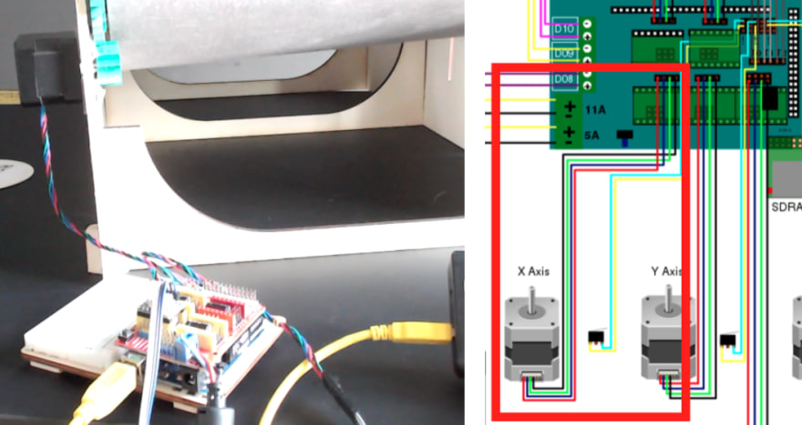
The stepper motor we use on our IIoT factory model is set up with the x-axis slot of an Arduino motor controller. The motor can only be started by supplying power via USB and stopped by pulling the USB plug. We added a startup sequence that slowly accelerates the motor up to a certain speed to optimize grip on the conveyor belt.
Cutting the conveyor belt of the IIoT factory model
The ideal material for your conveyor belt is thin, light, flexible, and durable. Depending on the total size of your model, the length of your raw material could be important, too.
For our IIoT factory, we used a 2m-long travel yoga mat. They are made of rubber—an ideal material— and are much thinner and lighter than regular yoga mats. We just cut it to the right length and glued the ends together to form a belt.
Assembling the IIoT factory model prototype
Let’s put together the components. Put up the wooden side panels stabilized with bridges. Put the conveyor belt correctly around the rollers and fit them into the notches. Make sure the one gear attached to a roller is in the corner where the motor is. Adjust the motor’s position so it’s cogwheel fits with the roller gear. Wire up the Arduino motor controller with the motor plug the motor’s USB power supply into a smart plug configured to work with IIoT Server. Make sure initially your smart plug is switched off.
Put your product-reader model on top of your IIoT-factory model and make sure the distance and angle of its camera enable it to read the QR code product data strips on the conveyor belt.
Running the IIoT factory model and recording the sensor events for the simulator
Once everything is assembled, put your product-data strip on the conveyor belt and keep an incident coaster in your hand to throw in at will. Start the conveyor belt by switching on the smart plug by sending an HTTP request to your local IIoT Server API.
curl --location --request POST <YOUR_RASPBERRY_LOCAL_IP>:4567/device_cmd' \
--header 'Content-Type: application/json' \
--data-raw '{
    "device": "conveyor_belt_plug",
    "action": {
        "cmd": "plug_on"
    }
}'
Throw in your incident coaster and the event data should be printed to screen. As we do this we record a trace file that we can replay in the simulator later. It looks like this:
{"name":"product_id","value":"123456","data":{"variant":"2b","color":"green"},"timestamp":1598365799.4526498}
{"name":"product_id","value":"123452","data":{"variant":"2b","color":"green"},"timestamp":1598365804.0941744}
{"name":"product_id","value":"123458","data":{"variant":"2c","color":"gray"},"timestamp":1598365809.2619932}
{"name":"product_id","value":"123451","data":{"variant":"2b","color":"green"},"timestamp":1598365816.2038214}
{"name":"product_id","value":"123457","data":{"variant":"2d","color":"red"},"timestamp":1598365820.4342263}
{"name":"product_id","value":"123453","data":{"variant":"2b","color":"green"},"timestamp":1598365824.5778954}
{"name":"incident","value":"FIRE_ON_BELT", "timestamp":1598365826.5328884}
You could either build by hand a software script with decision logic sending the HTTP request to switch off your smart plug if an incident is recorded on your own Kafka server. It would need to work well with the simulator we suggested building in our initial post.
Or > CONTINUE READING < the full version of the article on our Xapix blog and create a free Xapix Community Edition account.
Join our Home IoT community
We are working on follow-ups to this blog series and will post updates in our Discord community to inspire you with new ideas about how to use the Xapix IIoT Server once you have set it up. We would love to hear your ideas and collaborate!
Contact us on our Discord community channel if you would like to discuss this tutorial or if you have questions or feedback about the Xapix Community Edition. Or really anything else as well. We look forward to hearing from you!


Top comments (1)
This is a really insightful and well-structured article! I appreciate how you broke down the entire process of building the IIoT conveyor belt model and simulating incidents. The diagrams and code samples were especially helpful. Looking forward to more content like this—thanks for sharing!