


A reference architecture for running the whole AI assistant platform, models included, inside the customer's own facility
This document describes the third of three deployment patterns for an AI assistant platform. It is written for architects and platform engineers whose customer, or whose own organisation, has said: "No prompt leaves this building. Not to a vendor, not to a cloud model provider, not to anyone. Our network has no route to the internet."
Defence, sovereign functions, regulated manufacturing, some banks and hospitals. Fewer organisations need this than the first two patterns, but the ones who ask for it will check.
The structure is the same as Patterns 1 and 2. The design is independent of any product; the technologies named can be replaced.
Terms used throughout. The provider is whoever builds and signs the platform software: a vendor, or an internal platform team. The customer is the organisation whose facility the platform runs in. In this pattern the customer operates everything.
Prerequisites. A facility with its own network, GPU servers sized for peak inference, a Kubernetes distribution that can be installed offline, an internal certificate authority and time source, an approved process for carrying media in and out, and a team that can run Kubernetes, databases, Vault and GPUs without vendor access. A second data center if site-level recovery is required.
The three patterns at a glance
| Pattern | Data lives in | Operated by | Crosses the boundary |
|---|---|---|---|
| 1. Shared service | the provider's account, inside a residency boundary | the provider | every user's traffic, inside the boundary |
| 2. Control/data split | the customer's cloud account | the customer runs the data plane; the provider runs a control plane | signed software in, optional health metadata out |
| 3. Isolated site (this document) | the customer's building | the customer, everything | two signed files in, one optional file out |
For this pattern the three questions have short answers. The data lives in the building. The customer operates everything. Nothing crosses on an ordinary day. The rest of this document is what it takes to make those sentences true, and what it costs.
Architecture

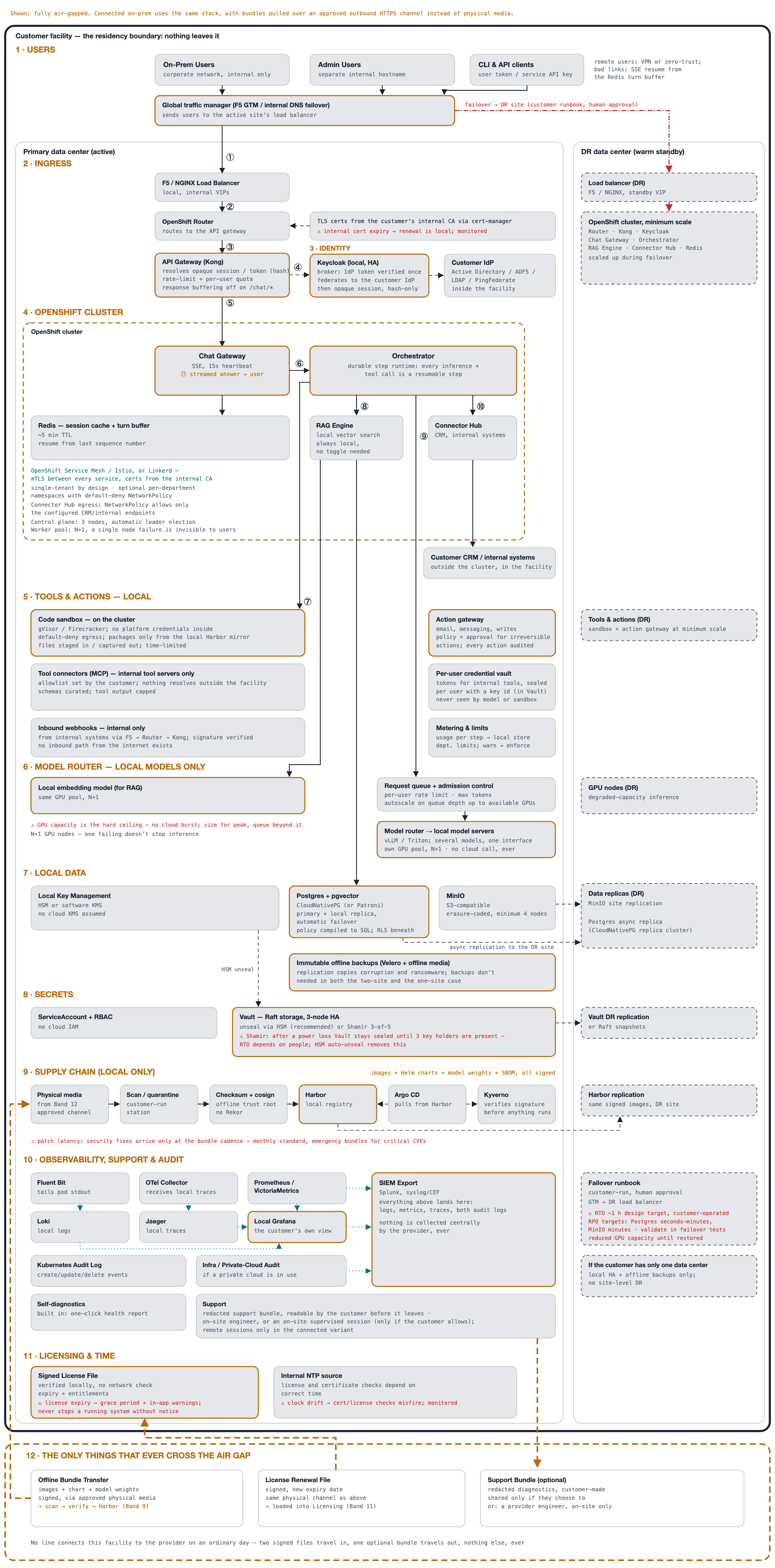
Four things to notice. There is no provider column. The provider builds, signs and prepares bundles and licences, and runs nothing in or near the customer. The models are local. A model router in front of vLLM or Triton on the customer's own GPUs replaces every cloud model call. The air gap is drawn as a band, not a line. The bottom of the diagram is the complete list of what ever crosses, with direction and condition. The ◆ marker appears nowhere, because there is no arrow to put it on.
A connected on-premises variant uses the same stack with one difference: bundles are pulled over a single approved outbound HTTPS channel instead of physical media.
Request flow
| Hop | Path | Protocol | Who opens it | Authentication |
|---|---|---|---|---|
| ① | Global traffic manager → load balancer | HTTPS/443; internal DNS steers to the active site | client | opaque session cookie or token, resolved at the gateway |
| ② | Load balancer → OpenShift Router | HTTPS/443 | load balancer | n/a (network hop) |
| ③ | Router → API gateway | HTTPS/443 | router | n/a (network hop) |
| ④ | Gateway → identity broker | HTTPS/443 | gateway | login and signing keys only; not on the chat path |
| ⑤ | Gateway → Chat Gateway | HTTP/8080 over mTLS | gateway | mesh identity |
| ⑥ | Chat Gateway → Orchestrator | gRPC over mTLS | Chat Gateway | mesh identity |
| ⑦ | Orchestrator → tools and actions | gRPC / HTTPS over mTLS | Orchestrator | mTLS; the sandbox holds no credentials; per-user tokens from the vault |
| ⑧ | Orchestrator → retrieval → pgvector | gRPC; then Postgres/5432 | Orchestrator, then retrieval | mTLS; database role from Vault; embeddings from a local model |
| ⑨ | Orchestrator → model router → local model servers | gRPC / HTTP over mTLS, inside the cluster | Orchestrator | mesh identity; admission control per user |
| ⑩ | Orchestrator → connector hub → internal systems | gRPC; then HTTPS | Orchestrator, then connector | mTLS; connector credentials from Vault |
| ⑪ | Streamed answer → Chat Gateway → user | SSE over HTTPS | already open | same session as ① |
The table is almost identical to Pattern 2's. The application does not change between patterns; the ground it stands on does.
Components
| Component | Role | Common choice |
|---|---|---|
| Global traffic manager, load balancers, router | Internal entry path; steers users to the active site | F5 GTM, NGINX, OpenShift Router |
| Internal CA | Certificates for every service, renewed locally | cert-manager with an internal CA |
| API gateway, identity broker, directory | Opaque session resolution; IdP token verified once at login | Kong, Keycloak, Active Directory or LDAP |
| Cluster: Chat Gateway, Orchestrator, retrieval, connector hub, Redis, mesh | The application, single-customer, mTLS between every service | OpenShift, Istio or Linkerd |
| Tools and actions | Sandbox with no egress, action gateway, MCP connectors to internal tools, per-user credential vault, internal webhooks, metering | gVisor or Firecracker, MCP servers |
| Model router, model servers, embedding model | Several local models behind one interface; request queue and admission control | vLLM, Triton |
| GPU nodes | Inference capacity, N+1 | customer-owned |
| Data | Postgres with pgvector, object storage, offline immutable backups | CloudNativePG, MinIO, Velero |
| Secrets and keys | Vault with HSM auto-unseal; local key management | Vault, HSM |
| Delivery | Scan station, checksum and signature verification with an offline trust root, local registry, GitOps, admission verification | cosign, Harbor, Argo CD, Kyverno |
| Observability and audit | All local; SIEM export; self-diagnostics | Fluent Bit, OpenTelemetry, Loki, Jaeger, VictoriaMetrics, Grafana |
| Licensing and time | Signed licence file verified locally; internal NTP | custom, NTP |
| DR data center | Warm standby: load balancer, minimum-scale cluster, GPU nodes, replicas | same stack |
Use cases
A facility with no route to the internet
Defence and sovereign environments, where the network is physically isolated and every transfer in or out is a controlled event on approved media. The pattern as drawn.
A regulated site that permits one outbound channel
Manufacturing, utilities, some financial institutions. The connected variant: the same stack, with software bundles pulled over one approved outbound HTTPS channel and nothing else leaving. Everything on the diagram stays as drawn except the physical media.
An organisation that cannot accept any cloud model provider
Even under their own contract and in their own region, some organisations cannot send prompts to a cloud model provider. Pattern 2 does not help them; this pattern does, at the cost of a local model class and local GPUs.
Design considerations
Security and privacy
Delivery across an air gap. The software pull of Pattern 2 is replaced by a bundle: images, the Helm chart, model weights and an SBOM, signed, written to approved physical media, and carried in through the customer's channel. Inside, it passes a customer-run scan and quarantine station, then checksum and signature verification against an offline trust root that shipped with the first installation. There is no call to a transparency log because there is nothing to call. The trust root is rotated through the same channel, with the old key signing the new one. From the local registry onward, the cluster behaves exactly as in Pattern 2: Argo CD pulls, Kyverno verifies before any pod starts, nothing is hand-applied.
Identity inside the building. The identity broker and the directory both sit inside the facility. The IdP token is verified once at login; the browser then holds an opaque session stored as a hash. CLI tokens and API keys resolve the same way. Certificates come from the internal CA and expiry is monitored, because there is no public CA to fall back on.
Tools and actions with nowhere to go. The sandbox has default-deny egress and takes packages only from the local registry mirror; there is no package index to reach, and this constraint belongs in the product documentation. Tool connectors run against internal tool servers only. The action gateway applies policy and approval steps for irreversible actions. Per-user tokens are sealed in a credential vault. Inbound webhooks come only from internal systems, through the same entry path, with signatures verified. Metering writes to a local store with per-department limits.
Models on the customer's GPUs. A model router fronts several local model servers behind one interface, with a request queue and admission control per user. A local embedding model serves retrieval on the same GPU pool. Nothing calls out. Model updates arrive as weights in the bundle, verified like everything else.
Data, keys and Vault. Authorization is one decision point: policy compiled into every query, row-level security beneath. Keys live in a local HSM or software KMS. Backups are offline and immutable, on separate media, because replication copies corruption and ransomware faithfully. Vault unseal uses HSM auto-unseal where possible; with Shamir shares, Vault stays sealed after a power loss until three of five key holders are present, which puts people in the recovery path.
Reliability
A DR data center runs as a warm standby: a load balancer with a standby VIP, a minimum-scale cluster, GPU nodes for degraded-capacity inference, and replicas of object storage, Postgres, Vault and the registry. Failover is the customer's runbook with human approval; the global traffic manager steers users to the surviving site.
Design targets, to be validated in the customer's own failover testing: recovery time about one hour; recovery point of seconds to minutes for Postgres and minutes for object storage; reduced GPU capacity until the primary site is restored. A customer with one data center gets local high availability and offline backups, and no site-level DR.
GPU capacity is the hard ceiling. There is no cloud to burst into. Size for peak, queue beyond it, and build N+1 so one failing node does not stop inference.
Operations
Everything is local: Fluent Bit, OpenTelemetry, Loki, Jaeger, VictoriaMetrics, a local Grafana, feeding the customer's SIEM together with cluster and infrastructure audit logs. Nothing is collected centrally by the provider, ever. There is no heartbeat because there is no line for it.
Support has to be designed for this: built-in self-diagnostics with a one-click health report, a redacted support bundle the customer reads before it leaves and sends only if they choose to, and an on-site provider engineer or supervised session only if the customer allows. Remote sessions exist only in the connected variant.
Patch latency is the operating cost that most needs saying early. Security fixes arrive at the bundle cadence, monthly as standard with emergency bundles for critical CVEs, and each needs a physical transfer, a scan and a verification.
A signed licence file is verified locally with no network check; expiry leads to a grace period and in-app warnings, never a silent stop. Licence and certificate checks depend on a correct internal NTP source, so clock drift is monitored as a first-class alert.
Cost
The customer pays for everything: GPUs, servers, storage, a second site, and the people to run them. Nothing is managed. This is the heaviest operating burden of the three patterns by a wide margin, and the only one with capital hardware cost.
Performance
Performance is bounded by local GPU capacity and model class. Only models that can be delivered as weights and served on this hardware are available; frontier hosted models are out of scope by definition. The request queue and admission control make the ceiling visible to users instead of letting requests fail.
Design alternatives
- The connected on-premises variant. One approved outbound HTTPS channel for bundles. Removes physical media and shortens patch latency, at the cost of one line out of the facility.
- Shamir unseal instead of an HSM. Cheaper, but puts people in the recovery path.
- One data center. Removes the second site's cost and gives up site-level DR; local HA and offline backups remain.
- Pattern 2 with a private model endpoint. For an organisation that can accept a cloud model provider under its own contract, Pattern 2 is lighter and offers more model choice.
What crosses the air gap
| Crossing | Direction | What travels | Who carries it | Can the customer refuse it? |
|---|---|---|---|---|
| Offline bundle | provider → customer, physical media | signed images, Helm chart, model weights, SBOM | the customer's approved channel; scanned and verified before the registry | yes; the running version keeps working |
| Licence renewal file | provider → customer, same channel | signed file: new expiry and entitlements | same as above | yes; expiry means a grace period and warnings, never a silent stop |
| Support bundle (optional) | customer → provider, manual | redacted diagnostics the customer read first | the customer | yes; never required; the alternative is an engineer on site |
That is the whole table. No heartbeat, no software pull, no model call, no sign-in assertion.
Trade-offs
- The customer runs everything, including GPUs and a second site.
- Model class is fixed by hardware: local open-weight models only.
- Patch latency at the bundle cadence.
- Support works blind: bundles the customer chooses to send, or a visit.
- People in the recovery path unless an HSM is used for unseal.
- No provider commitments on recovery. Every figure is the customer's to validate.
When to choose this pattern
Choose the isolated site when the rule is "no prompt leaves this building, and there is no route out", when the organisation can operate Kubernetes, GPUs, databases and a second site, and when a local model class meets the need. If a cloud model provider under their own contract is acceptable, Pattern 2 is lighter. If they want the provider to run it, Pattern 1.
Deployment outline
Everything arrives as a bundle and is installed by the customer.
- First bundle. Images, Helm chart, model weights, SBOM, the offline trust root and the signed licence, on approved media. Scan, verify the checksum and signatures, load into the local registry.
- Foundation. The Kubernetes cluster, GPU nodes, Postgres with pgvector, object storage, Vault with HSM auto-unseal, the internal certificate authority and time source.
- Delivery path. Argo CD pointed at the local registry, Kyverno with the offline trust root, the scan and quarantine station as a standing procedure.
- Identity and entry path. The identity broker federated to the internal directory, the global traffic manager, load balancers, router and API gateway with internal certificates.
- Application, tools and models. Argo CD applies the signed charts: Chat Gateway, Orchestrator, retrieval, connectors, mesh, the tools-and-actions layer, the model router and model servers with the delivered weights.
- Observability, licensing, support. Local telemetry into the SIEM, the licence file loaded and verified, self-diagnostics and the support-bundle procedure agreed with the customer.
- Second site and backups. The DR data center with replicas and a minimum-scale cluster, offline immutable backups, then a failover test that replaces the design targets with measured results.
Detailed topology
The full design in twelve bands. The hop numbers match the request flow table above. Open the figure at full size to read the component notes.
Choosing between the three patterns
| Pattern 1: shared service | Pattern 2: control/data split | Pattern 3: isolated site | |
|---|---|---|---|
| Where the data lives | provider's account, inside a residency boundary | customer's cloud account | customer's building |
| Who operates | provider | customer (data plane), provider (control plane) | customer, everything |
| Model | provider's model accounts, pinned to the region | customer's own cloud model providers | local models on the customer's GPUs |
| Software delivery | provider deploys | customer pulls signed software | signed bundle on physical media |
| Support | provider sees its own system | redacted bundle, or break-glass on the customer's terms | redacted bundle or on-site visit |
| Operating burden on the customer | low | heavy | heaviest |
| What crosses the boundary | every user's traffic, inside the boundary | software pull, opt-in heartbeat, support; model call to the customer's own provider | two signed files in, one optional file out |
Three patterns, one application, the same three questions. If you can answer them for your own system, with every crossing drawn and every figure labelled for what it is, you can answer the questions a security review will ask.
What's next
This is part 3 of a three-part series. The other parts are also linked in the series box at the top of this article.
- Pattern 1, the shared service (SaaS): the provider runs everything inside a residency boundary.
- Pattern 2, the control/data split (customer cloud): the customer runs the whole data plane in their own cloud account.


Top comments (0)